Decorative Mouldings:
Frederick Wilbur explains how to carve classical mouldings.
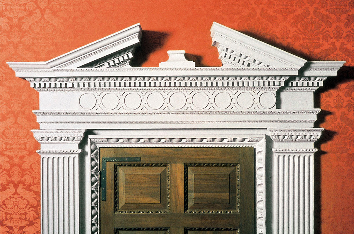
Fig 1: Door architrave with Doric pilasters, full entablature and open pediment. Gunston Hall (1759), Lorton, Virginia
The most common architectural decoration is the moulding which, plain or fancy, is used for a variety of reasons: to create shadows, and therefore depth; to divide surfaces visually, creating balance or pleasing proportion; or to create a finished delineation to a corner, joint or edge. There are functional uses as well: covering or weatherproofing joints, hanging pictures (as well as framing them), protecting plaster walls, and so forth. Mouldings, for our purposes, are strips of wood (or edges of wider pieces) which have a distinctive shape or, more properly, profile; and it is this profiled part which is carved. Most of the plain profiles can be embellished with decoration; it is the repetition of design units which makes them effective in breaking up the inherent linear quality of mouldings. Figs 1–5 show some characteristic examples.
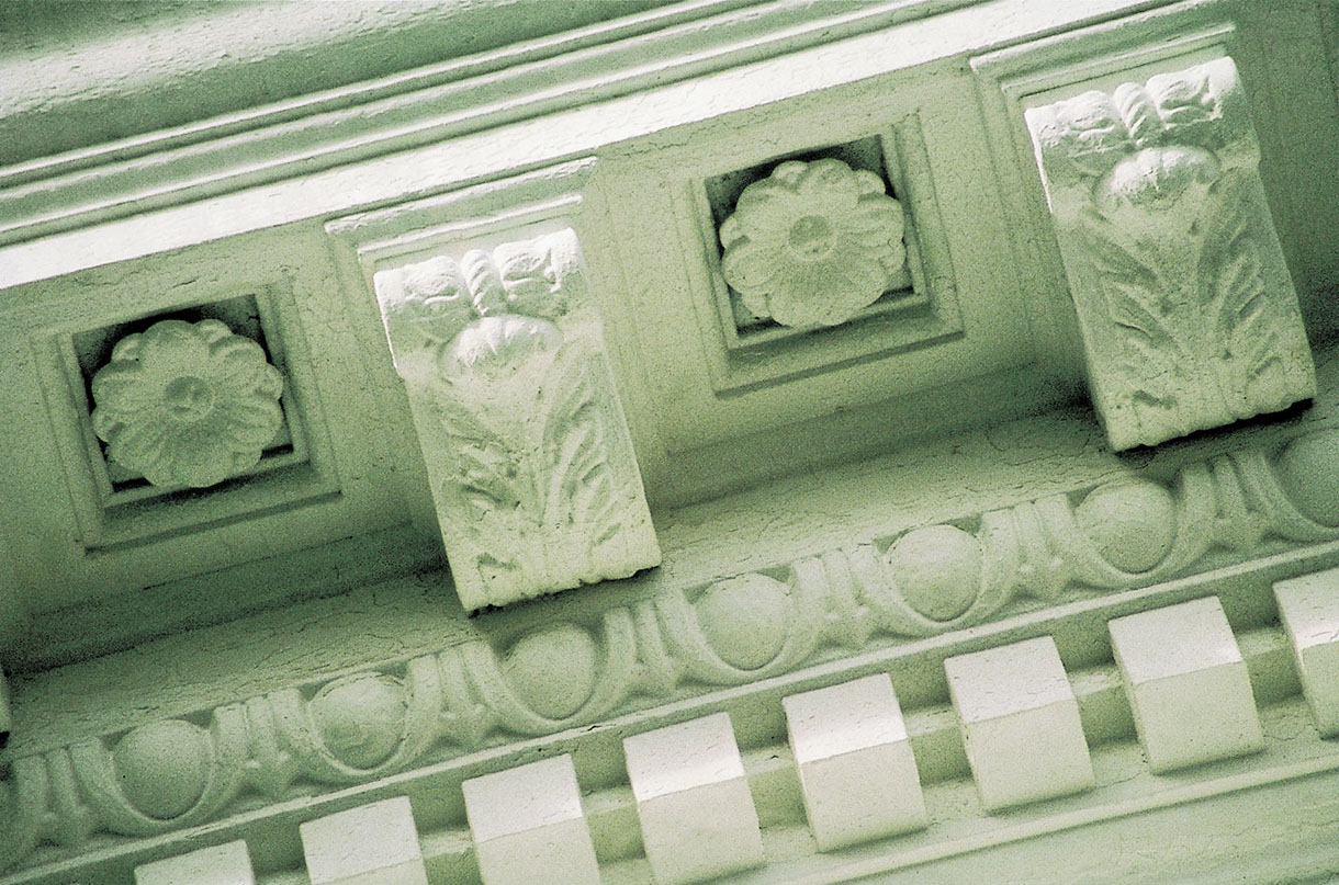
Fig 2: A cornice at Jefferson’s University of Virginia, Charlottesville, showing (from top) modillion blocks and rosettes, egg and dart, and dentils
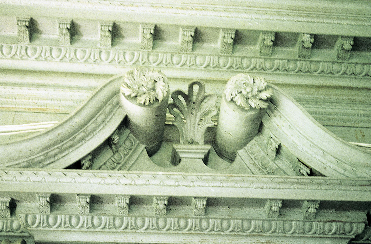
Fig 3: Scrolled pediment on an overmantel at Drayton Hall (1742), Charleston, South Carolina; the mouldings are egg and dart and simple waterleaf
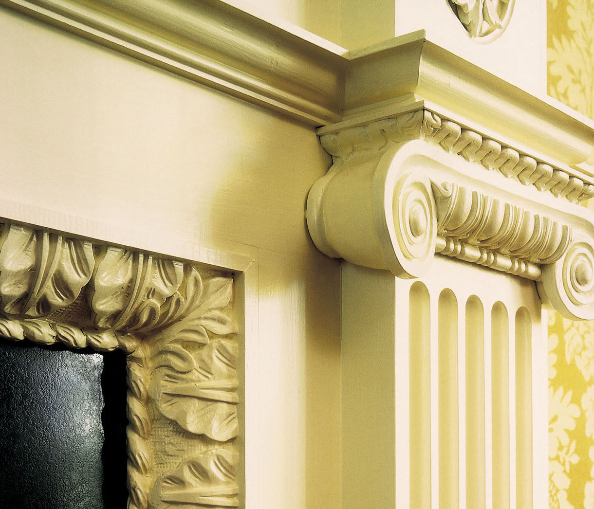
Fig 4: Detail of a mantel by the author, showing Ionic pilaster with waterleaf abacus, and ovolo backband
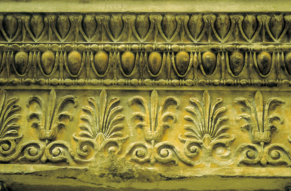
Fig 5: A fragment from the cornice of the Erechtheion in the British Museum, showing (from top) leaf and dart, egg and dart (each with bead and reel beneath) and anthemion
The plain profile can be fabricated or ‘run’ by a computerised moulding machine, stationary shaper, portable router, hand plane or scratch stock. The architectural millwork firm specialising in custom work will use machinery to produce the profiles needed; they may use standard cutters or have someone on staff to grind the desired profiles. The shop without such equipment can use a combination of saws, hand-held routers and hand planes to fabricate the necessary shapes, particularly in the case of the smaller and more standard profiles. Large coves can be made on the tablesaw. Large rounds can be shaped with an ordinary bench plane. The small facets left from the plane can be smoothed by the use of a curved scraper, or with sandpaper; if the round is to be carved, many of the facets may be eliminated anyway. The tablesaw can be used to cut away excess material or to define the extent of a profile before moulding plane or scratch stock is used.
There are many varieties of router bit available through numerous tool distributors, but their use may represent a compromise, especially when an existing profile is to be duplicated. It is possible to modify high-speed steel bits, but most moulding bits are carbide-tipped and harder to alter.
Before the Industrial Revolution, mouldings were made exclusively by hand plane and scratch stock. Each plane produced a specific profile, so the joiner required a chestful of them if he intended to undertake fine woodworking. There were planes for beads, coves, ogee profiles, ovolos, reeding, tongue-and-groove joints and so forth. Some planes combined several profiles, such as cove, fillet, and ovolo, or bead and ovolo. The descriptive terms used by the practical joiner or carpenter for these profiles are not necessarily those used by the architectural historian: for example, round planes make cavettos, beading planes make astragals, while the common or Roman ogee, the Grecian ogee and the reverse ogee planes all make different varieties of cyma profile.
There have been dozens of different profiles and combinations throughout history, but most classical ones can be assigned to a few families based on simple geometry (Fig 6). Most, in fact, are segments of a circle (or ellipse) or combinations of arcs in conjunction with flats or fillets. These families are: the half-round or astragal (more generically called the bead), with its big brother the torus; the convex quarter-round or quarter-ellipse, called the ovolo; the cavetto or cove, which is a concave quarter-circle or quarter-ellipse, with its sister the scotia, which contains two different arcs; and lastly the combination of two opposite arcs (one concave and one convex), the cyma or ogee. It must also be mentioned that many designs can be incised or cut into a narrow flat band: these include the wave, the Greek key, the guilloche, chip-carved designs, and many more. This article discusses the astragal, the ovolo and their cousins, as well as flat mouldings.
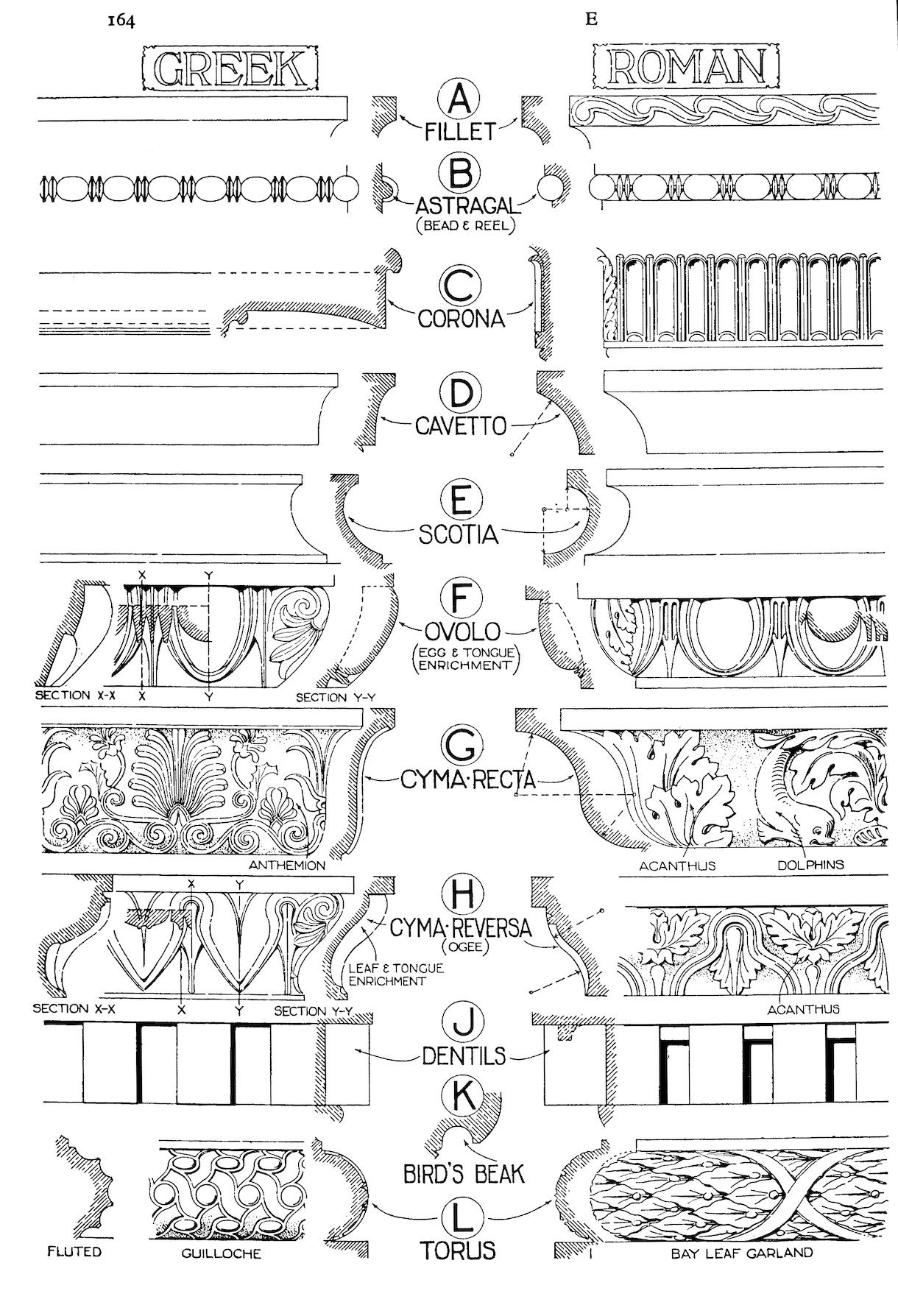
Fig 6: Drawing of moulding profiles comparing Greek and Roman treatments, from Sir Banister Fletcher,
A History of Architecture on the Comparative Method
Layout
The carver, then, is working on a seemingly tricky piece of material with curves and/or sharp edges in profile as well as a running pattern along its length. It will become obvious in this chapter that there is a correlation between the profile and the type of decoration which can be cut into it, and that the profile often dictates the tools used.
Mouldings, by their very function, have to change directions around a room or piece of furniture, and the joint or corner is usually a mitre, regardless of how the moulding is applied. In quality work, whether door casing, mantel or cornice, the most prominent elevation is laid out symmetrically. That is, the centreline falls between two of the main decorative units so they are equal in number on either side of the centreline; though at times a main unit is bisected by the centreline. Some designs – spiraled ribbons and gadrooning, for instance – have an orientation to right or left, so they originate from the centreline and proceed in opposite directions towards the ends or corners. So it is from the centreline that the basic increments of the pattern are laid out.
The point at which the mitre cuts through the design determines whether adjustments are required in order to fit a whole unit in before the joint. Most patterns can be broken in two places: either at the midpoint of a design unit, so that the unit itself ‘turns’ the corner, or between units. (Some mouldings have several alternating units, affording a wider choice of break-points.) Many patterns can be ‘stretched’ if necessary over several repeats so that the mitre joint falls in one of these two places. Not all designs divide neatly at the mitres, the egg and dart (an ovolo profile) being the primary example of one that does not – a half or a third of an egg meeting a half-dart would look ridiculous. The Greeks realised the awkwardness of this situation and either left the corner unornamented or ‘covered’ the design with a leaf, one half of the leaf falling on either side of the joint. The latter solution has been adopted almost without exception ever since. The idea is that the concealing leaf tricks the eye into assuming that the underlying design is continuous, regardless of how the pattern actually would work out if the leaf were not there. Fig 7 shows a typical example.
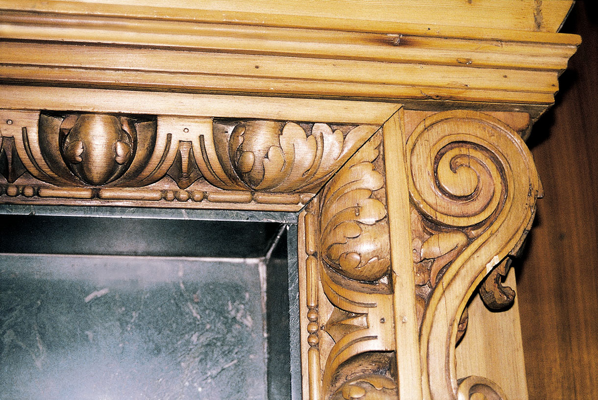
Fig 7: Egg and dart moulding, showing the use of leaves to mask the mitre joint
Short lengths of moulding, as in ‘dog-legs’ on door casings or returns on cornices, if too short for a full unit, are sometimes treated with simplified or abbreviated renditions of the design (Fig 8). One moulding which is not amenable to this treatment is the egg and dart.
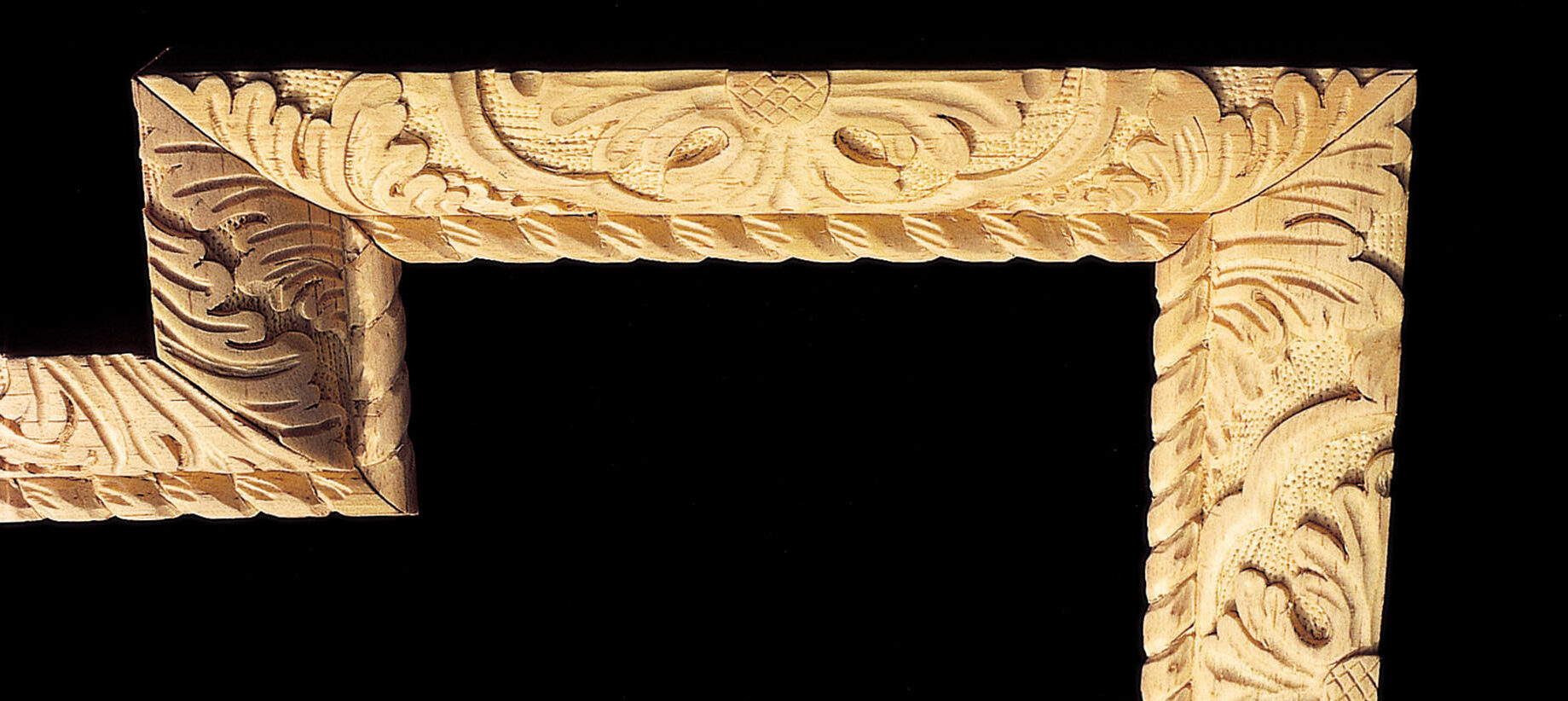
Fig 8: An example of the author’s work, showing how an abbreviated version of a foliage design may be used for a short return section or ‘dog-leg’ in a crossetted frame
In order to have a nice-looking joint, the moulding should be mitred and fitted dry before laying out the carving. The mitred pieces should be labelled in sequence so that the carving at the joints can be aligned accurately and appear as though carved in situ. Some short pieces could actually be glued together prior to carving. Rarely would the situation arise that a moulding is actually carved in place, however.
While laying out the design, remember that a flat drawing in elevation does not account for the actual curvature of the material; the design may need to be stretched in its apparent height to accommodate this three-dimensionality. This may, in turn, distort the proportions so much that the design along the length requires adjustments as well. Correction is made in the selection of the tools to be used.
You may have to redraw the repeating unit several times to make it look comfortable on the profile. After these necessary adjustments, use dividers to transfer the repeating unit to the remaining pieces of moulding. Check measurements frequently, as a fractional variation tends to be cumulative and will ‘creep’. Once a satisfactory layout has been achieved on one piece, it is prudent to lay out all pieces before work begins.
Three layout aids
Marking frame
If there are multiple pieces of the same length, a simple marking frame can be made to mark increments simultaneously on all pieces (Fig 9). The lengths of moulding should not be unmanageably long: door-panel moulding is a good occasion to use this device. The frame consists of two strips of wood fastened to adjacent edges of a rectangular piece of plywood so as to form a right angle. If the profiled moulding pieces are placed together against one fence and the ends pushed until they touch the adjacent fence, the centrelines on all pieces should match. A framing or try square can then be moved along the first fence to mark across all pieces at once.
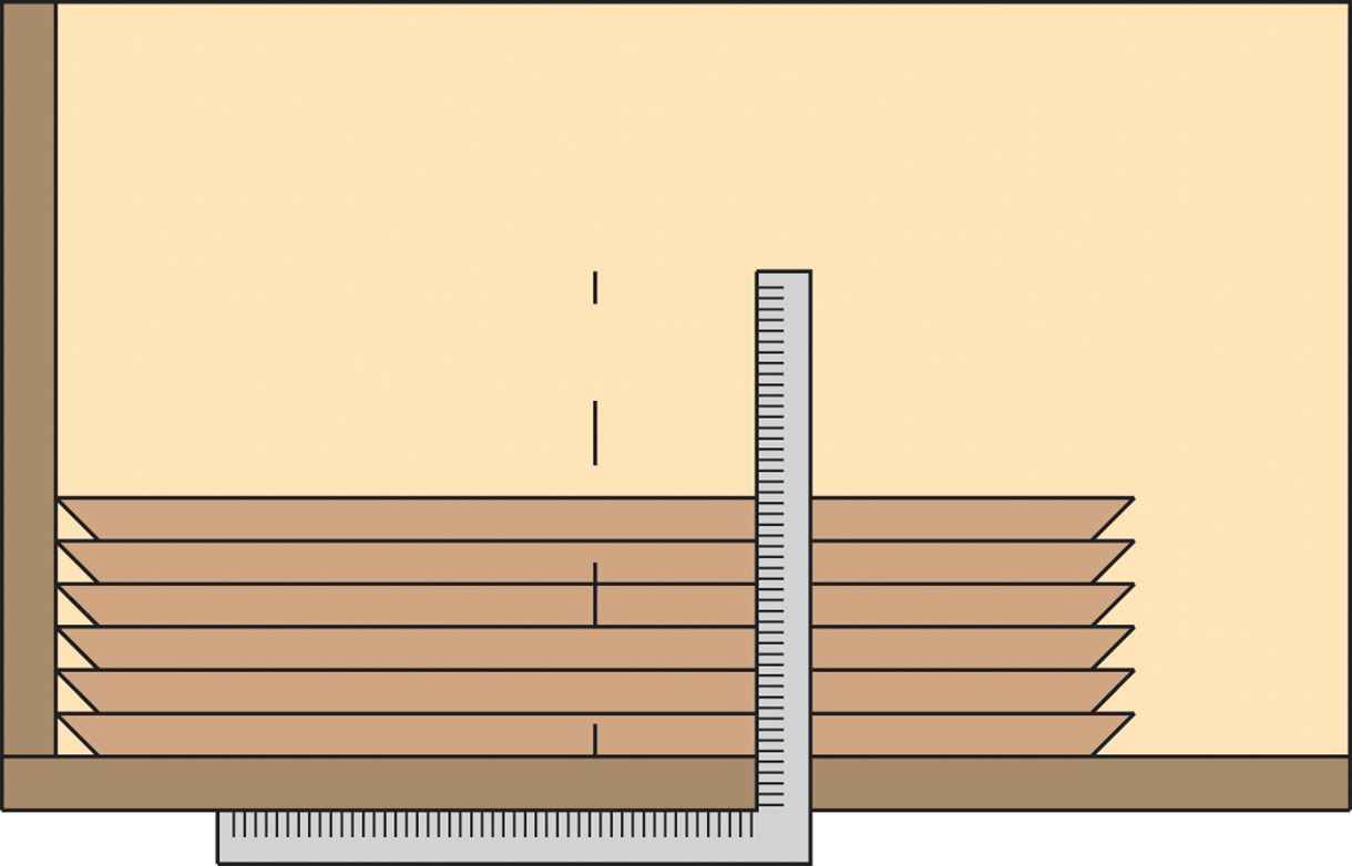
Fig 9: The marking frame: a simple jig for marking out mouldings of uniform length
Marking wheel
Another aid to laying out unit increments is the marking wheel (Fig 10). This is simply a wheel with sharp points around its circumference, mounted in a handle. It is essentially a modification of the pounce wheel or scrivener’s wheel used to space lines on parchment, or the seamstress’s marking wheel. (These obviously have a limited range, even if modified by removing some of the teeth.) This gadget works best on smaller mouldings such as bead and billet, waterleaf, and small egg and dart. Determine the required increments by carving a sample piece. The measurements between design units or half-units will determine the circumference of the wheel or disc. It is easy to divide the disc accurately into eight parts using 45° divisions, especially if the stock is dressed square to begin with. For example, if the increment desired is 16mm between leaves, beads, etc., multiply by 8 to obtain the required circumference, which in this case is 128mm. Then divide this number by π (pi – approximately 3.14) to find the diameter necessary (remember: C = πd, where C is the circumference and d the diameter). Half this diameter gives the radius needed to draw the circle on the disc.
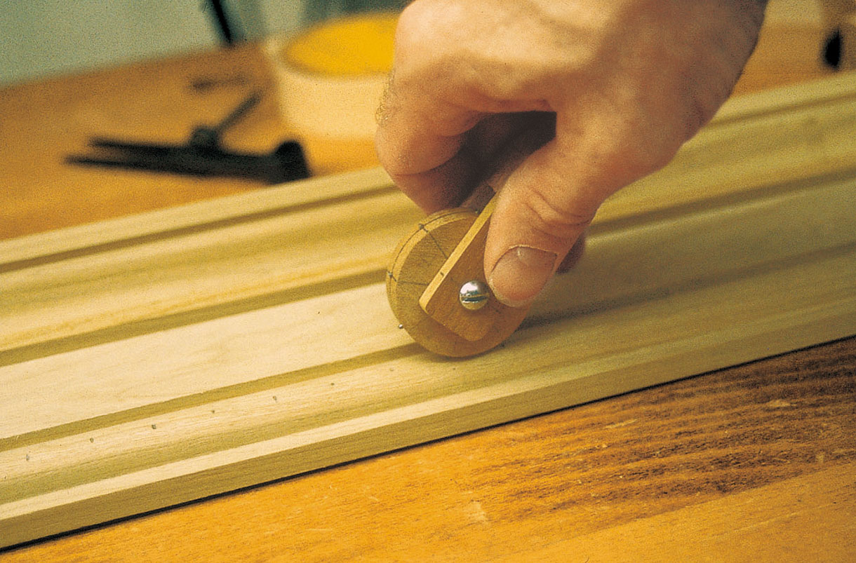
Fig 10: The marking wheel in use
Choose the bolt which will be used as the axle of the marking wheel, and drill a hole the same size through the centre point of the disc blank. Cut out the circle with a bandsaw or coping saw, allowing plenty of room on the outside. Put the bolt through the hole and use a nut to tighten the disc to the bolt. The bolt is then mounted in a Jacobs chuck on the lathe, and the disc is turned down until the circumference line is just shaved off. With a flexible plastic ruler or seamstress’s cloth measuring tape, check to see that the divisions are equal and accurate. The disc should then be turned about 1mm smaller, to allow for the length of the points which are inserted next.
With a try square, carry the division lines onto the edge of the disc. Use a sharply pointed awl to mark each division in the middle of the edge. Hammer brads into these points, as straight in line with the division marks as possible, and with a wire cutter snip the nails off close to the disc. The raised peak created by the snippers is usually enough to mark the wood, but if preferred the points can be filed. In fact, a little adjustment can be made if necessary by filing the brad on one side only. Note that if the brads project too far the intended increment will be increased.
The handle is then made from 19mm square stock and turned on the lathe. Leave a sufficient length of square at one end for cutting a slot on the tablesaw to house the disc. On the tablesaw, cut a slot somewhat longer than the disc radius, to accommodate different-sized discs. Drill a hole near the end of the slot with the same bit that was used to drill the disc. Rub a little paraffin wax on the wheel and mount it in the handle, then test it on a scrap piece of wood. If half of the original increment is required (8mm in our case), run the wheel down the moulding in the usual way and then begin again, setting one point halfway between the previous marks.
Gauge block
One additional tool often useful in marking lines along the run of a moulding is the gauge block (Fig 11). It is advantageous to have such lines when you need to locate a similar feature on each unit; a good example is the ‘eyes’ of acanthus leaves. The gauge is a flat piece of stock of 13mm or so thickness, with a fence attached at 90° to it. (Most mouldings have a 90° back or fillet which the gauge block can run against.) In the face of the stock drill holes of suitable size to hold hexagonal lead pencils snugly. The critical point is to locate these holes where they will mark the desired features. They should be measured directly from the moulding which has been partially laid out or, better still, from the carved sample. With the fence against the back of the moulding and the top face riding the moulding, push the pencils through the appropriate holes until they touch the moulding. Using the fence to guide the gauge, you can then move the pencils the length of the moulding.
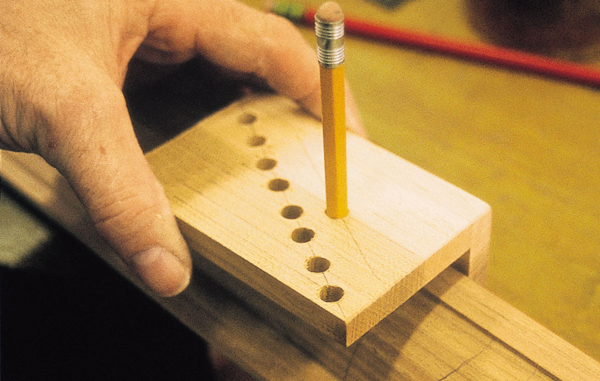
Fig 11: The gauge block in use. The multiple holes allow more than one pencil to be used at a time if necessary
An old marking gauge with a hole drilled in it for a pencil can also be used, but the advantage of the gauge described above is that several pencils can be used to mark several lines simultaneously; it can also be used in tight situations where the arm of the marking gauge might be in the way. Related trades may have various tools or aids which can be adapted to woodworking. The popularity of quilt-making has spawned a number of them, particularly plastic layout grids and squares.
Creating patterns for layout
Some designs, such as bead and billet or egg and dart, are simple enough to warrant only the barest laying out. More complex designs, such as acanthus leaves, will require a more sophisticated layout and a pattern. Because a concave or convex surface is to be marked, the material chosen for the pattern needs to be flexible, but able to retain the integrity of the profile. For sustained use, a thin metal such as aluminium roof flashing or sheet brass will serve well. Making the metal stencil can be time-consuming and tricky at best, but the time saved in layout will offset any frustration in making a good stencil. One long side of the metal should be referenced to one edge of the profile by butting it up against a flat on the profile itself (Fig 12) or on the bench top.
A 90° flange formed on one edge of the pattern can also serve to reference it against the edge of the profile.
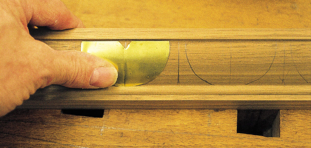
Fig 12: Setting out egg and dart with the aid of a metal pattern. The pattern butts against the fillet at the
top of the moulding and the astragal at the bottom; the central notch is aligned with the penciled increment lines
For larger profiles without an obstructing fillet, sheet rubber of sufficient hardness and thickness (gasket rubber) can be used. A board which has a saw kerf along its length serves as a base. The moulding to be marked is fixed to the board with its face at the edge of the groove. The rubber stencil is moved along this groove and pressed onto the profile. The groove prevents the rubber from shifting.
Making a metal template
Transfer the design to the metal, or tape a paper pattern to the metal. There are two methods of actually cutting the stencil: the metal blank can be kept flat on a scrap board for cutting and then bent afterwards to conform to the profile, or it can be bent on a scrap piece of moulding and retained there for cutting. In either case, the actual tools to be used in carving the moulding are used to make the pattern. Take time to visualise how the stencil will be used: are you marking the areas to be left or those to be carved away? Do you need to leave connectors between cutouts? Make sure the metal is referenced correctly, and proceed to match the curvature of the gouges to the basic elements of the pattern, cutting through with a tap of the mallet. You will need to resharpen the tools, but if the volume of moulding is sufficient, the time spent is well worth it. In making any stencil, the intention is to lay out the main cuts quickly, not necessarily marking every detail, but keeping the work crisp and tidy. A pencil is then used to transfer the pattern to the moulding at each pre-measured unit. Check the layout carefully, as from here on the carving is
done by eye.
Carving mouldings
Because mouldings are repeating and symmetrical patterns, the carver can produce large quantities efficiently. The usual method is to work the entire length with the same cut, then reverse the cut and work back to the beginning. The cure for the inherent boredom of such a procedure is to acquire a rhythm, and with it some degree of accuracy.
One aid to achieving this desired efficiency is to practise first on an extra length of the profile, so that the selection of tools and the sequence of cuts can be determined beforehand. Most mouldings are in shallow relief, and the technique of ‘stab and relieve’ is the general rule, keeping surface modeling to a minimum; in a sense, the profile of the moulding itself provides the surface modelling. When replicating an existing design, the sweep of the tool must be matched to the shape of the design. Producing mouldings is not so much a question of accuracy as consistency. Accuracy begins with layout and selection of tools, while consistency begins with experience in execution. Practically speaking, variations will occur and, unless these are grossly asymmetrical, the eye will be hard-pressed to detect them once the moulding is installed. This, of course, is the more true the further the moulding is from the viewer.
When working hardwood mouldings, a mallet may be needed to set in. This should not be too heavy, as too much of a strike would ‘pop out’ delicate pieces. Putting down and picking up the mallet for every placement of the tool is inefficient. This problem can be solved by turning your own mallet on the lathe, giving it a thin handle so that it can be held while the same hand is moving the gouge to the next repeat. A tough hardwood such as beech (Fagus spp.) or dogwood (Cornus florida) works well. The mallet head only need be 54–57mm in diameter, with a handle of 22mm diameter at its narrowest. The overall length is 235mm. Depending upon the wood, it will weigh 230–280g; the weight is not as important as the length of handle (Fig 13).

Fig 13: A mallet suitable for setting in mouldings (see text for suggested dimensions)
Holding the profiled material
As with all work to be carved, the moulding needs to be held solidly on the bench, and although the usual metal bench dogs or clamps serve well for most projects, we must be careful not to dub the sharp long points of mitred pieces. There are several ways to hold mitred profiles: wooden bench dogs can be modified, or special jigs made.
Using scrap hardwood, make two bench dogs with wider than usual heads (Fig 14). They do not need to have spring tensioners, but should fit snugly into the dog holes in the bench. Their protruding ‘chins’ rest on the bench top. In the middle of the face of each dog, place a small screw, leaving 6mm of the shank exposed. Remove the screw heads with a hacksaw and then grind or file the shanks to points. With a chisel, carefully pare the corners of the face backward from the screw so that the cheeks form an acute angle. With the dogs placed in the appropriate holes, the vice is then closed so that the points grab the mitred ends of the moulding; the resulting marks will be hidden when the mitre is assembled. This method works well for medium-sized mouldings. The drawback is that only one length of moulding can be done at a time (or two, on a bench with a double row of dog holes).
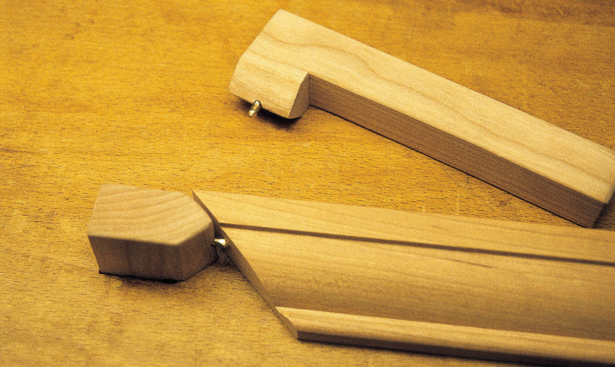
Fig 14: Bench dogs for holding pieces with mitred ends
When a number of pieces of the same length are to be carved (as with moulding for door panels), a jig can be made to hold the mitred pieces. A length of hardwood is used as a supporting fence upon which cleats are mounted to hold the ends of the moulding. Depending upon the length of the moulding and the available area of bench top, several lengths may be mounted on one jig (Fig 15). The ends of the short cleats are cut at 45°. Drill screw holes in the cleats, then mount one of them to the end of the fence. Place a pre-mitred piece of moulding snugly into the 45° space. Locate a second cleat at the other end, overlapping the mitred end slightly so that it holds it tightly. This second cleat can be made double-ended (as in the photo) to accept a second piece of moulding in line with the first. This fence or jig is then clamped to the bench top. The cleats can be remounted for different lengths of moulding.
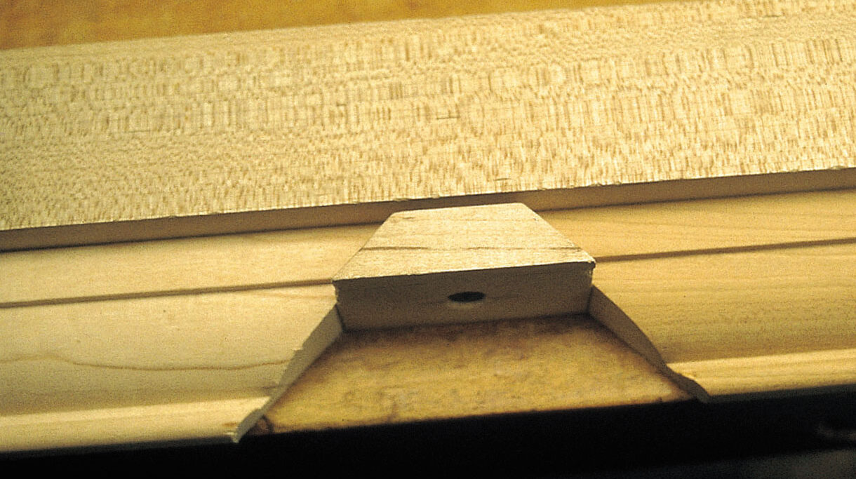
Fig 15: The jig for holding multiple pieces with mitred ends
Another method is to screw through a waste board and into the back of the moulding, then clamp the waste board to the bench. This works well for small mouldings and those which are carved right to the edge, such as spiral designs on astragals. The waste board protects the bench top from errant gouge marks.
It is not very practical to glue long lengths of moulding to a backing board. This often recommended method should be avoided, since it adds time to the job in clean-up, and with fragile carvings there is always the danger of breaking pieces when trying to extricate the carving from the paper. Most architectural pieces can be held by vice, clamp or screw, or wedged in routed recesses or between fences. Never nail a moulding directly to the bench top, as the moulding might split in its securing or removing, to say nothing of scarring the bench top for life.
Designs for flat surfaces
There are many embellishments that can be achieved with a minimum number of tools, and which do not require a moulded profile to be effective. They are carved directly into a flat surface and, though not mouldings by definition, they may serve the same purpose. They are used for narrow pieces sandwiched in among other mouldings, and are not to be confused with the frieze. They can consist of isolated designs or of a continuous repeat. Evenly spaced flutes, zigzag designs, incised lines, overlapping circles resembling coins or scales, are all examples of this technique (Figs 16 and 17). The simplest such decorations are chip-carved designs. The term ‘simple’ is not meant pejoratively, though we tend to think of these as vernacular motifs; accuracy in layout is essential just because these shapes are simple.
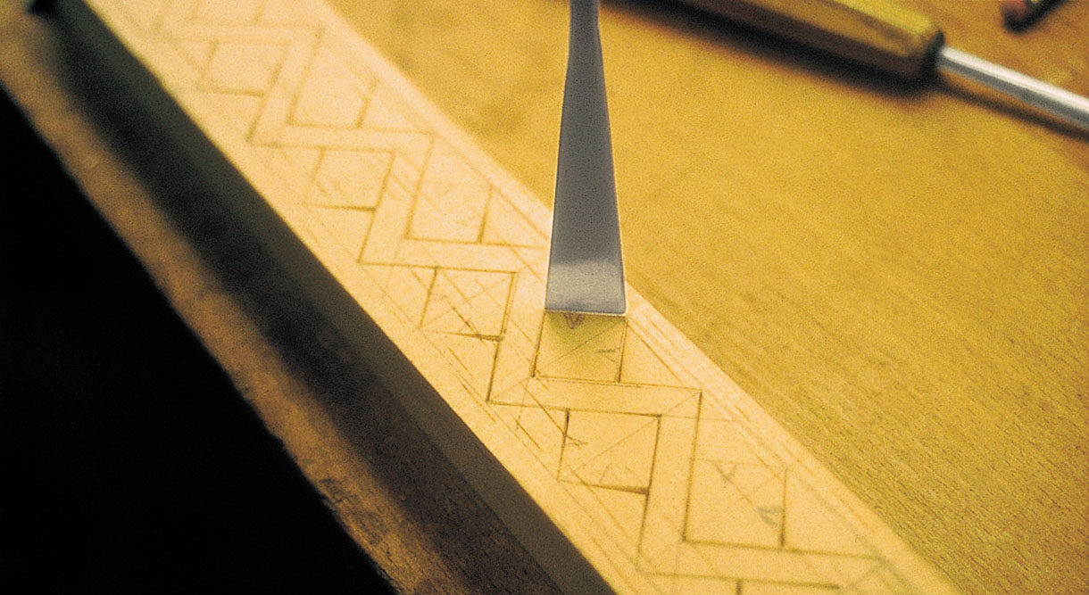
Fig 16: Setting in simple surface decoration; the fishtail chisel is angled to produce cuts which slope back from the surface
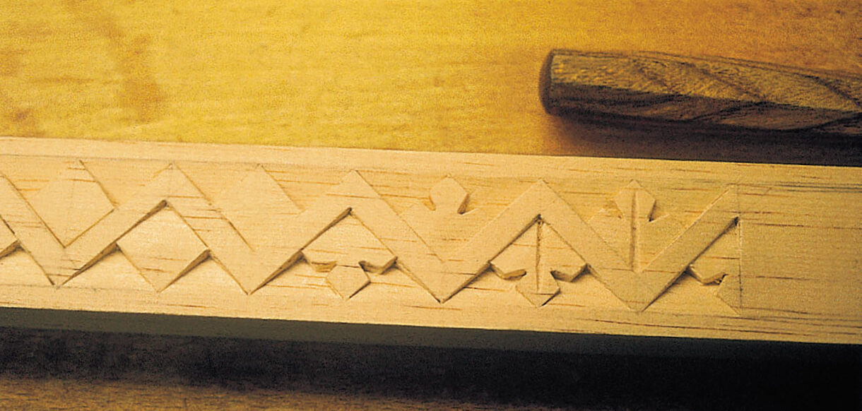
Fig 17: Subsequent stages in carving the same design. The result is very like traditional chip carving
The flute
Flutes can be carved using a single gouge, which is first stabbed straight in to make a stop-cut and then used to form the groove or flute which meets it. However, the acute corners created by this method are sometimes hard to clean out. For this reason the stopped flutes shown in Fig 18 tend to be preferred, but these require two tools: a firmer chisel modified to a round point, and a semicircular gouge. Flutes are commonly used on the cove mouldings of picture frames, mantels and architraves, and can be grouped between rosettes to create the triglyphs of an ersatz Doric frieze. These sorts of designs are found on vernacular furniture and buildings everywhere, but often these techniques are incorporated into more complex elements, and it should be obvious that the few examples cited here only hint at the possibilities.
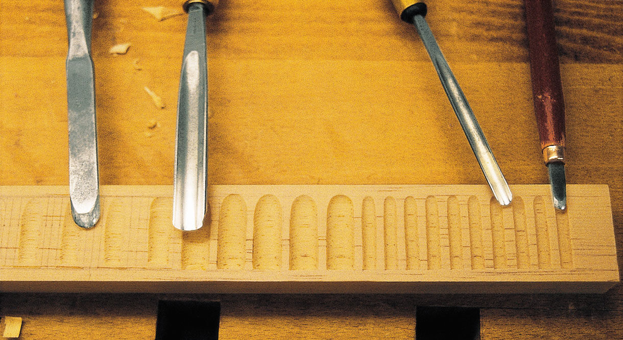
Fig 18: Two sizes of flutes in a flat surface, with the tools used to cut them: a round-ended chisel and a semicircular gouge


