Seaside Inspired Island Table:
Dave Rigler explains how he made the Island Table, a stunning piece inspired by a seaside landscape
Dave Rigler explains how he made the Island Table, a stunning piece inspired by a seaside landscape
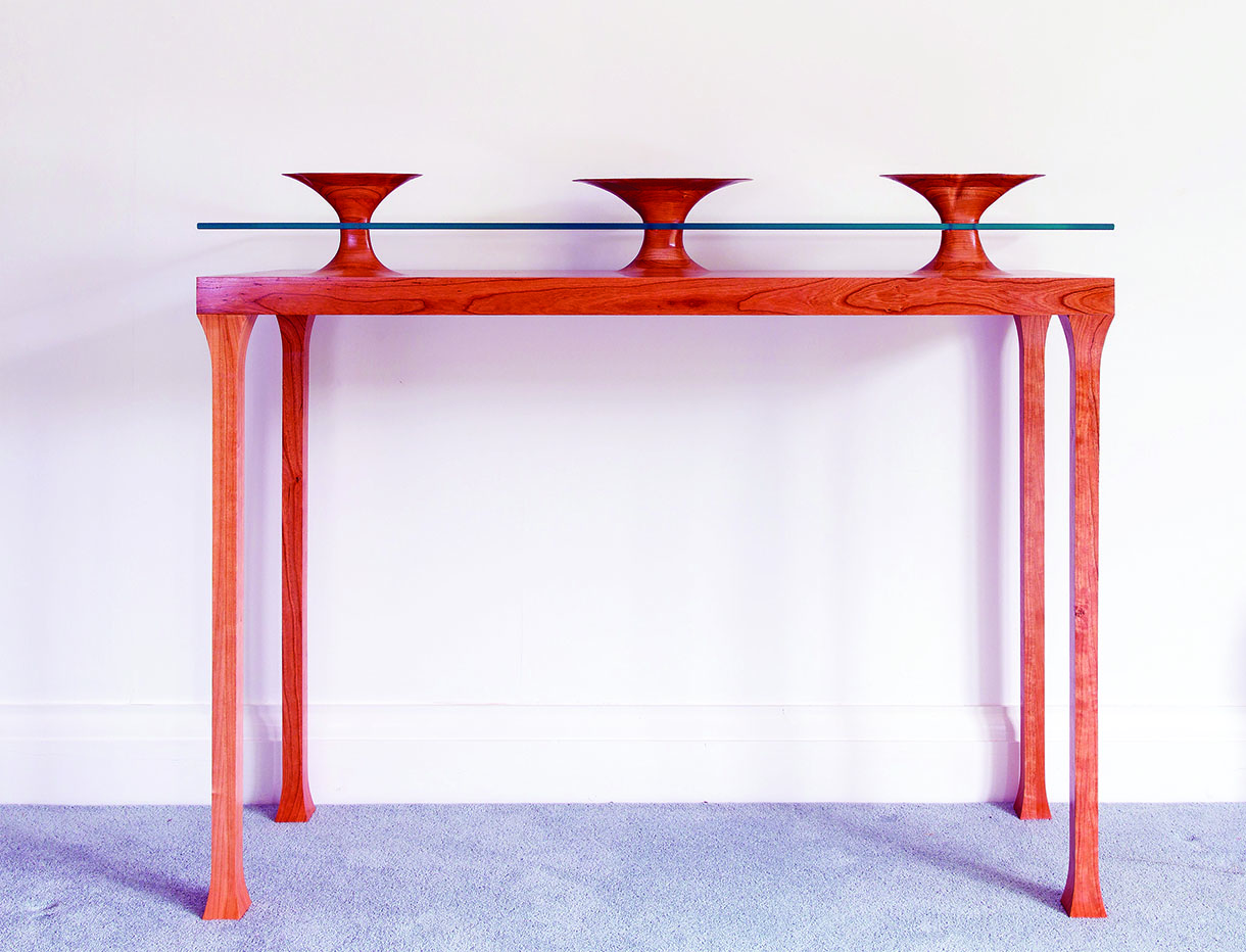
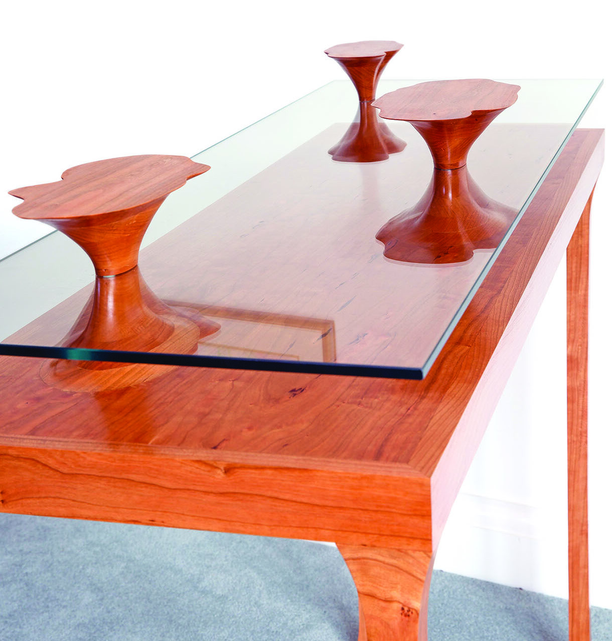
The design of this table is very personal to me, evoked from my observations and enduring memories of the natural sweeping overhangs created by the constant erosion of the sea on a group of islands off the coast of Kenya.
The glass of the table represents the sea and the wood surface the seabed. This is a departure from the ‘form follows function’ philosophy that I generally work to; in this case it was definitely the other way round
as the function has taken second place to the form!
I chose to use cherry (Prunus spp.) for this project because of its interesting figuring.
Construction
The basic construction of the table was relatively simple and conventional. The challenges for me lay in how to produce the islands, incorporate them into the table top relatively seamlessly and have the glass appear to surround them. Planting islands straight onto the top of the table would require the production of very fragile feather edges, which would also be difficult to glue down and the subsequent finishing with scrapers and abrasive would be likely to adversely affect the surrounding areas. The solution I adopted was to make the base of the islands plug into recesses in the surface and carry out the majority of the blending on the base before assembly. The trick is to produce bases that are a piston fit into the recesses.
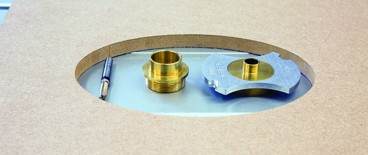
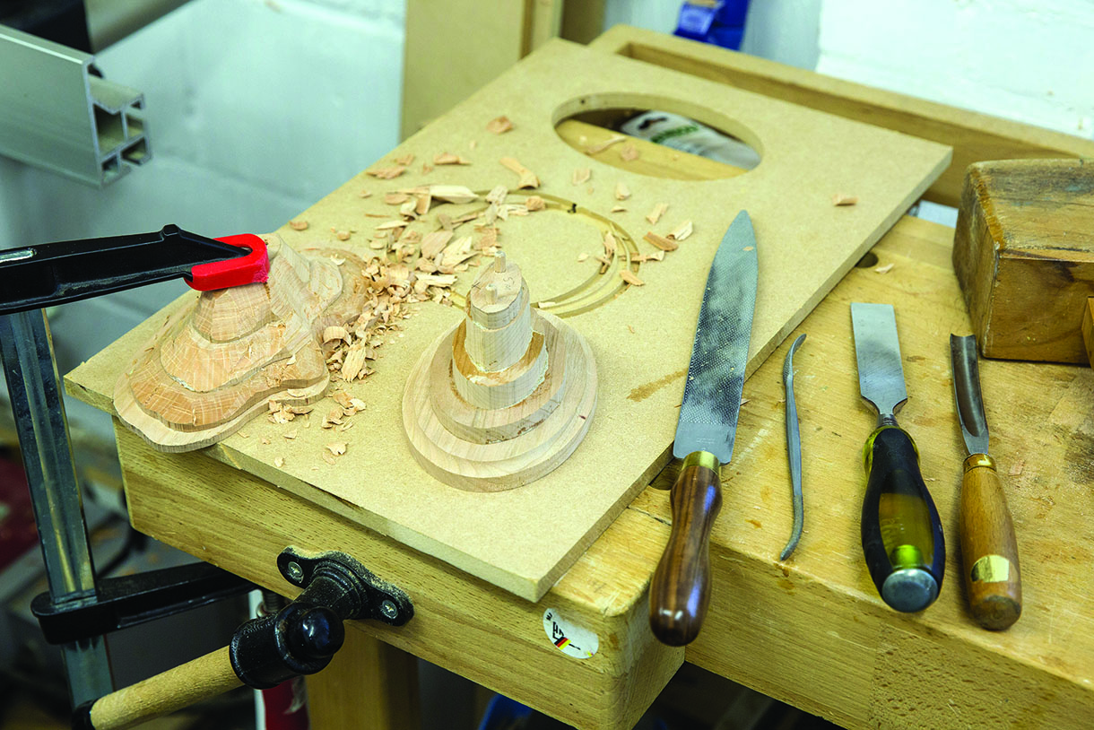
The tools and template used to create the hole and insert for the islands
Island to table top interface
To achieve the tight island to table top interface needed, I used a router and template approach. The shape of the islands dictated that an ellipse rather than a circle would be best and fortunately I had some Trend templates that suited. The photo above right shows the tool set I used. Note that I created an MDF template from the Trend plastic one to give better support to the router and plenty of facility to clamp it to the workpieces.
Basically, if you select the right combination of sizes of cutter and guide bushes you get a nice tight fit. In this case the cutter was 6mm. The hole in the table top was cut using a 24mm bush and the cherry insert was cut using a 12mm bush. One refinement I made to the cherry insert was to use a 12mm bowl cutter to rout a 5mm deep recess into it first. This provided a clear and precise line to set the insert level with the table top and created the starting point for the blend into the island form. I also invested in a set of precision UJK brass guide bushes, which were excellent.
One word of caution when cutting the base. As well as firmly clamping the template and the cherry blank securely together, make sure that what will become the base is also securely anchored to prevent it moving when fully cut through and damaging the profile. I did this by screwing it down to the sacrificial MDF surface under the blank in positions that would not be exposed in the later forming process.
This process was carried out after veneering the table top but before adding the frame. Care was taken to ensure the cherry inserts had their grain oriented to match the table top.
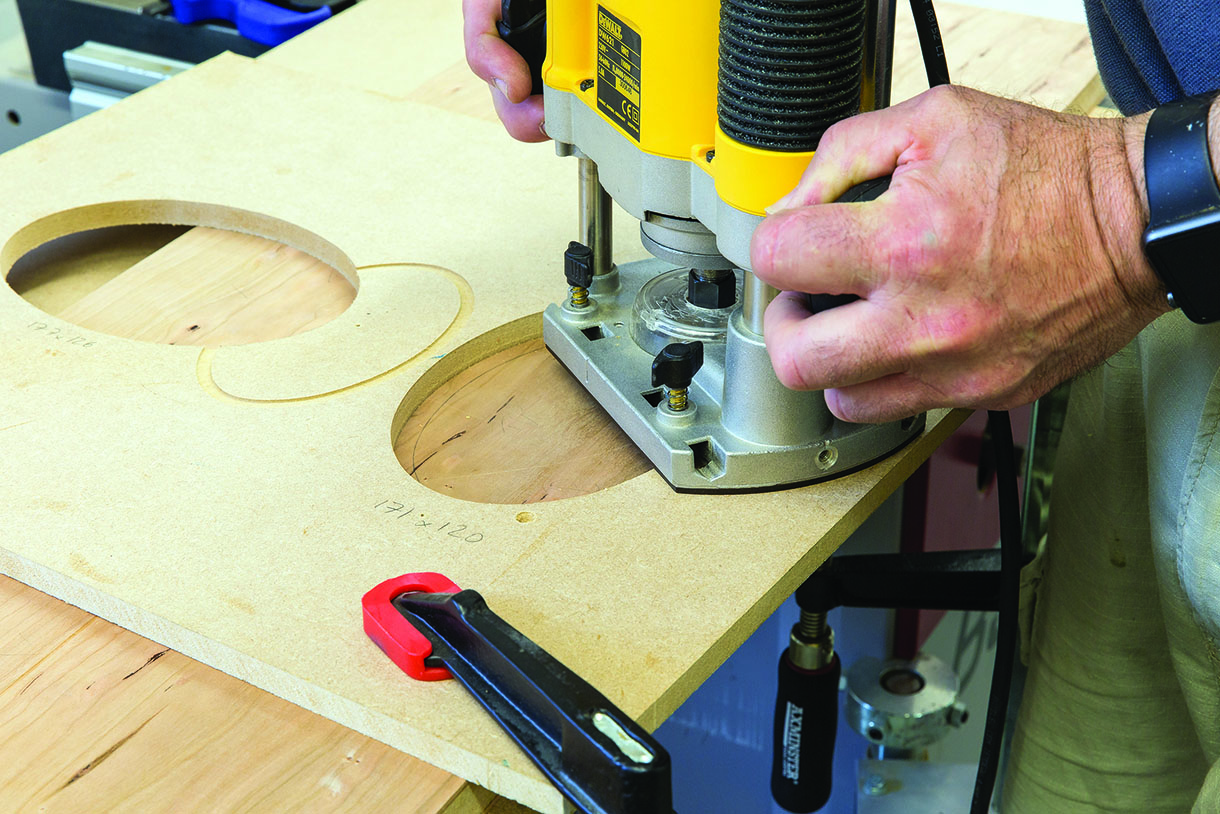
Hole for the island being routed out
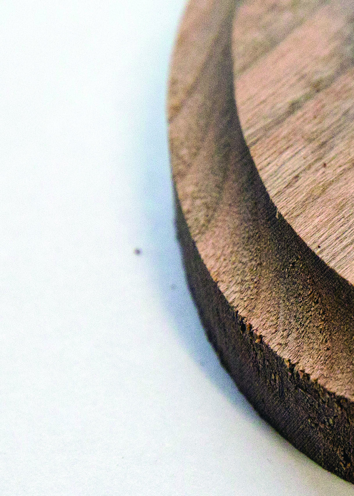
Rebate on the island insert to aid alignment to the table top
Island design and making
An experienced carver would be able to just take a lump of wood and hew a wonderful shape from it, but that ain’t me I’m afraid so I resort to some CAD tools to help me out! Humour aside, I do find the ability to visualise from all angles on screen a powerful aid before committing to wood. Very much the equivalent of a physical maquette.
The islands needed to be freeform and organic in appearance but also blend into a geometric oval at the base. To achieve this in 3D CAD I created three 2D profiles, one at the base, one in the centre (glass level) and one at the top. The base shape was simply an oval, smaller than the planned oval table insert size. The centre was another smaller oval. The top was freeform drawn, copying my pencil sketch ideas, using a ‘Spline’ tool that smoothed the curves. I then used a ‘Lofting’ tool to generate a 3D solid that sweeps through and blends between these three elements. Using this method I was able to quickly adjust the 2D profile shapes and sizes until I was satisfied with the overall 3D form. Finally, a ‘Fillet’ tool was used to blend the 3D island into the horizontal insert. In all, I created three islands of different sizes.
To physically make these islands I used a bread-and-butter approach. This would give me a series of profiles to carve to, helping me maintain the form developed in CAD. I sliced the islands horizontally to create nine sections. The depth of each section was determined by the rate of curvature of the profile, i.e. 5mm at the top, 25mm at the centre. Finally I added two holes passing through the islands vertically to act as reference/assembly holes. It was then easy to plot each of these sections on paper and use them for templates.
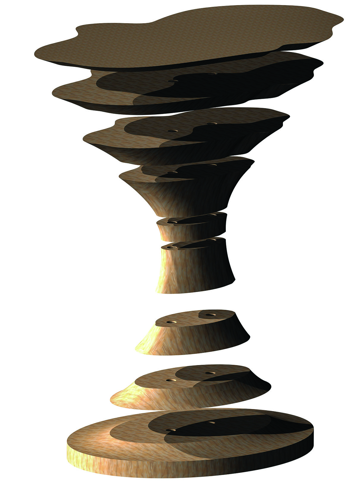
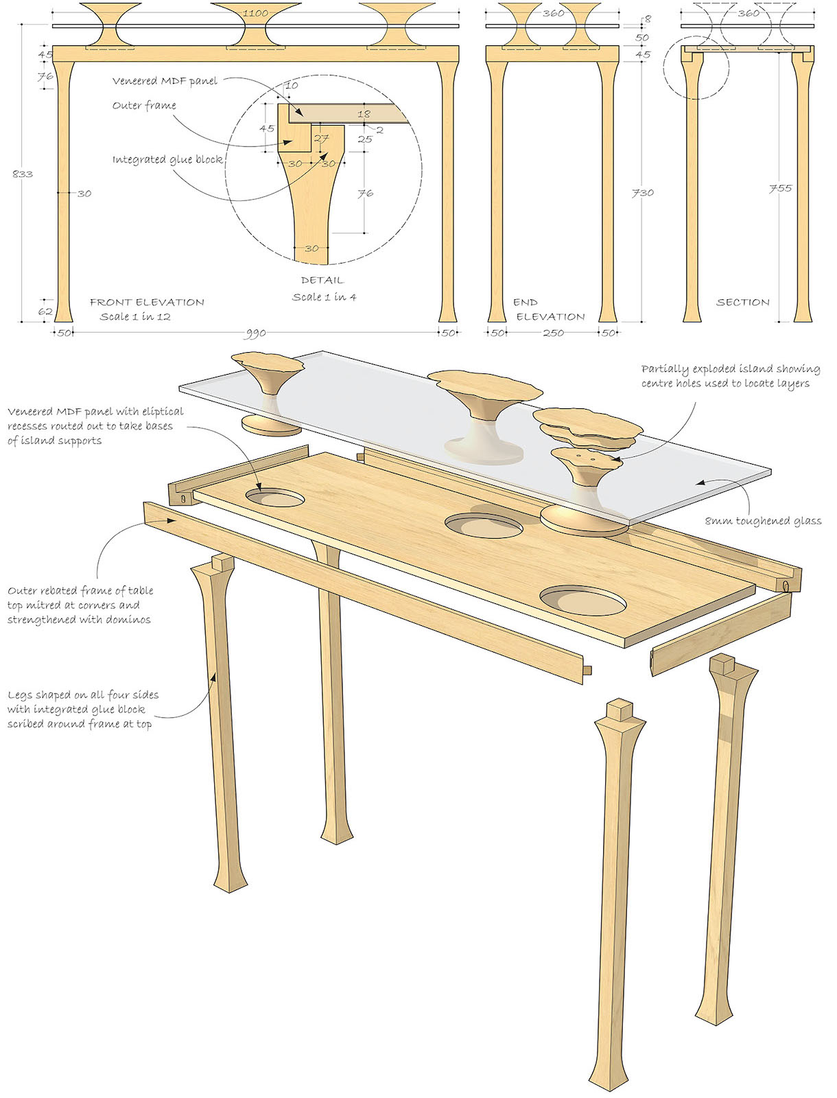
CAD exploded rendering of the island layers
Various blanks of cherry were thicknessed to the sizes required, templates glued in place and bandsawn to the profile. Before committing to the cherry I made a trial run using some scrap softwood. From this I learned two things. First, I needed to make the islands in two halves initially, as this gave better access for the chisels to do the rough shaping. Second, to achieve a tight glue line all round it was best to glue up one layer at a time to achieve adequate clamping. The two reference holes were used to align the cherry sections during gluing and once this was done the fun could start. The tools I used to get to rough shape
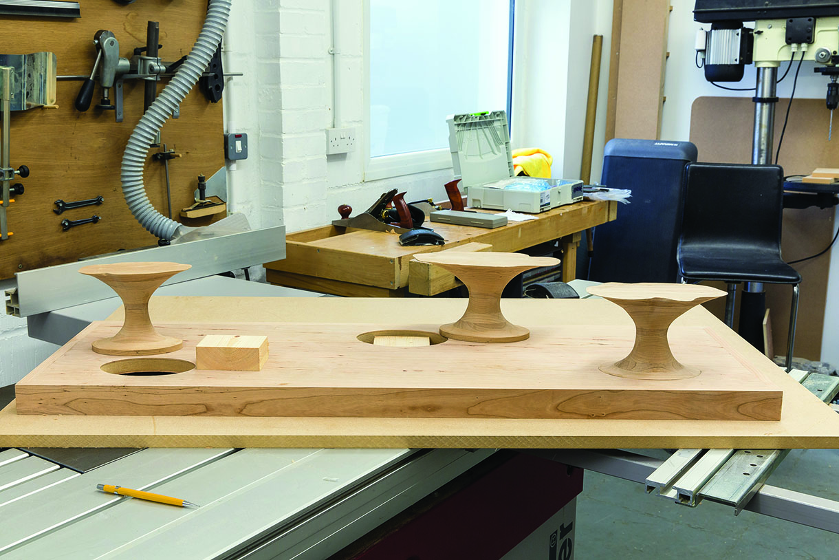
were chisels, a gouge, rasp and a riffler. After the bulk of the waste material had been removed and a rough form established, the two halves were joined together so that the final form could be created as a smooth sweeping shape from top to bottom. This final forming of the shape was carried out predominantly with rasp, riffler, abrasive papers and a Kirjes sanding drum, which was particularly effective. With 80 grit it could remove material very quickly, so care was needed. The transformation from start to finished form can be seen in the ‘before and after’ photo below.
The final operation on the islands at this stage was to bore back down and clean out the reference holes with a 6mm drill to just beyond the sea line. These holes will provide the alignment and fixing of the islands through the glass on assembly.
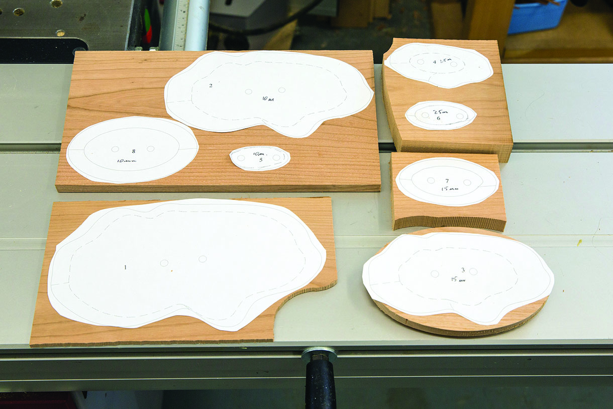
Templates on the cherry blanks ready for bandsawing
Island halves being carved to rough shape
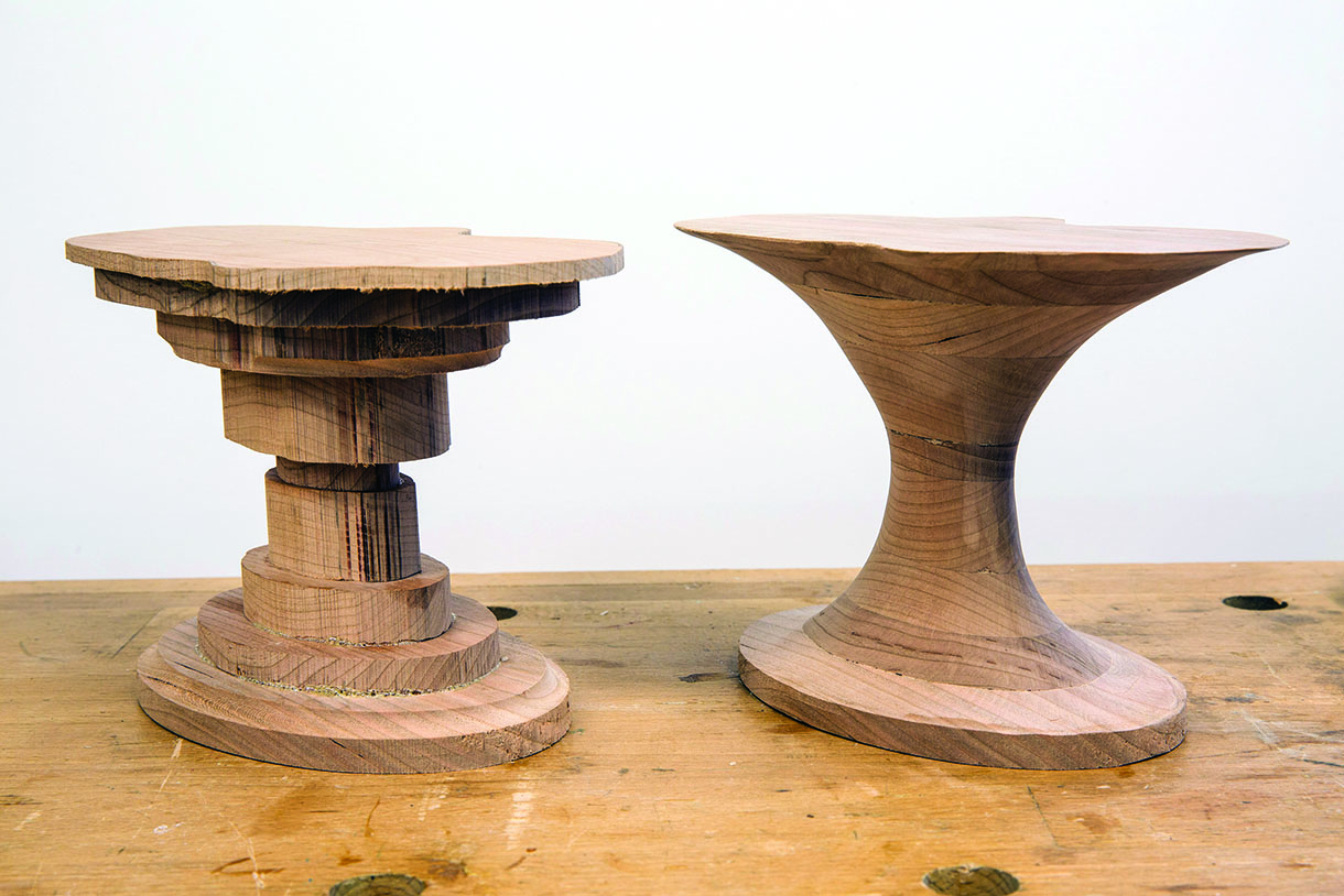
Before and after view of an island
The table top
The table top was constructed from a rebated frame surrounding a veneered 18mm MDF panel. Although there are some good ready veneered boards available, I chose to cut my own veneers for two reasons. First, I wanted to be able to be more selective over choice of pattern for the table top. That is, I was looking for something that was more heavily figured and representative of a seabed. Second, I was concerned that the thickness of manufactured veneers (0.4–0.6mm) might be vulnerable to breakthrough during final finishing of the island to top interface.
Initial planing of a few planks of cherry revealed one with lovely figuring so I used this for the face veneers. I bandsawed them at approximately 2.5mm and to longer than the full table length. I used two consecutive ones for the surface, laid side by side but one reversed, to achieve the best balance and appearance. Two further veneers were cut from a less attractive board for the underside.
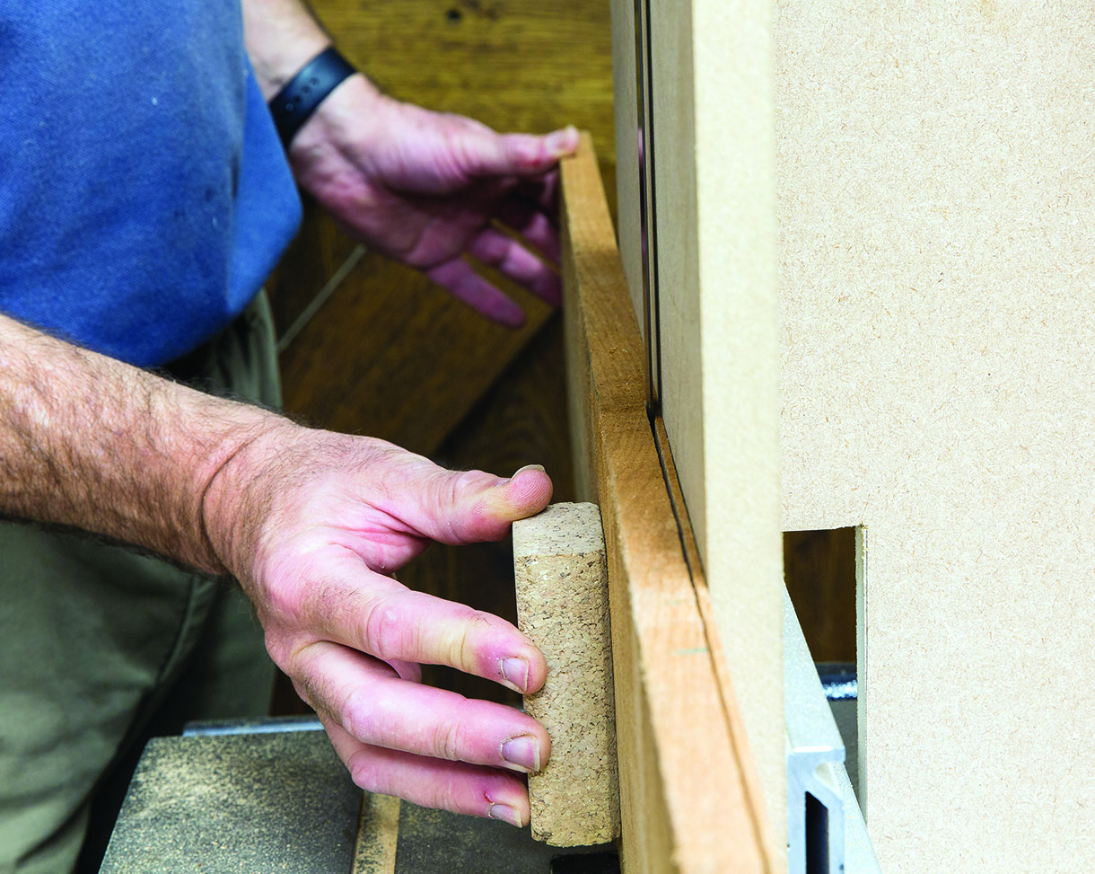
These veneers were then bonded to the MDF using an Airpress Vacuum bag. The finished board was finally sized ready for assembly to the frame. The frame construction was straightforward, the prepared lengths rebated on the spindle moulder and then mitred. Some time was spent hand planing to achieve exact size
to the veneered board. Each corner was reinforced with a Domino and the whole glued up.
Bandsawing the veneers for the table top
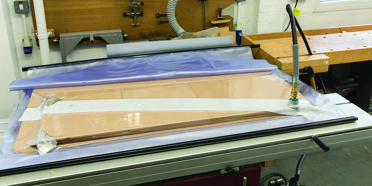
Vacuum pressing the veneers to the MDF substrate
Assembling the table top frame and veneered panel
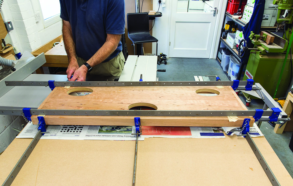
Assembling the islands in the top
Incorporating the islands into the top was probably the most worrying part of the project but in the end it actually proved fairly straightforward. To constrain the islands in the table while gluing I placed the top on a flat, even surface of MDF and positioned individual thicknessed timber blocks under each island such that they were flush with the surface. As a further alignment aid, a sheet of MDF was placed over the top of the islands to ensure they remained horizontal and level with each other.
Once the glue was completely set it was time to part the islands at the lower level of the glass line. To ensure that the parting lines and surfaces were absolutely level with each other and parallel to the table surface, the same setup and fence as used for cutting the veneers on the bandsaw was used again, with the exception that I changed to a finer blade. With the fence reset, each top piece was then cut again to remove the equivalent of the glass thickness. The cut surfaces were lightly cleaned up with a low angle block plane.
With the island tops removed the blending of the islands to the table top could be more easily carried out using scrapers and abrasives only. Final sanding of the whole assembly was also completed down to 400 grit. The island tops were also finish sanded at this stage.
Assembling the islands to the table top
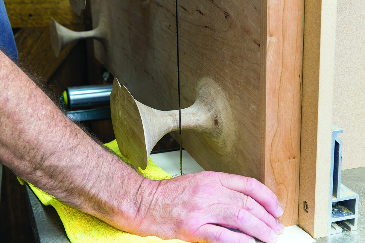
Parting the island tops at glass level
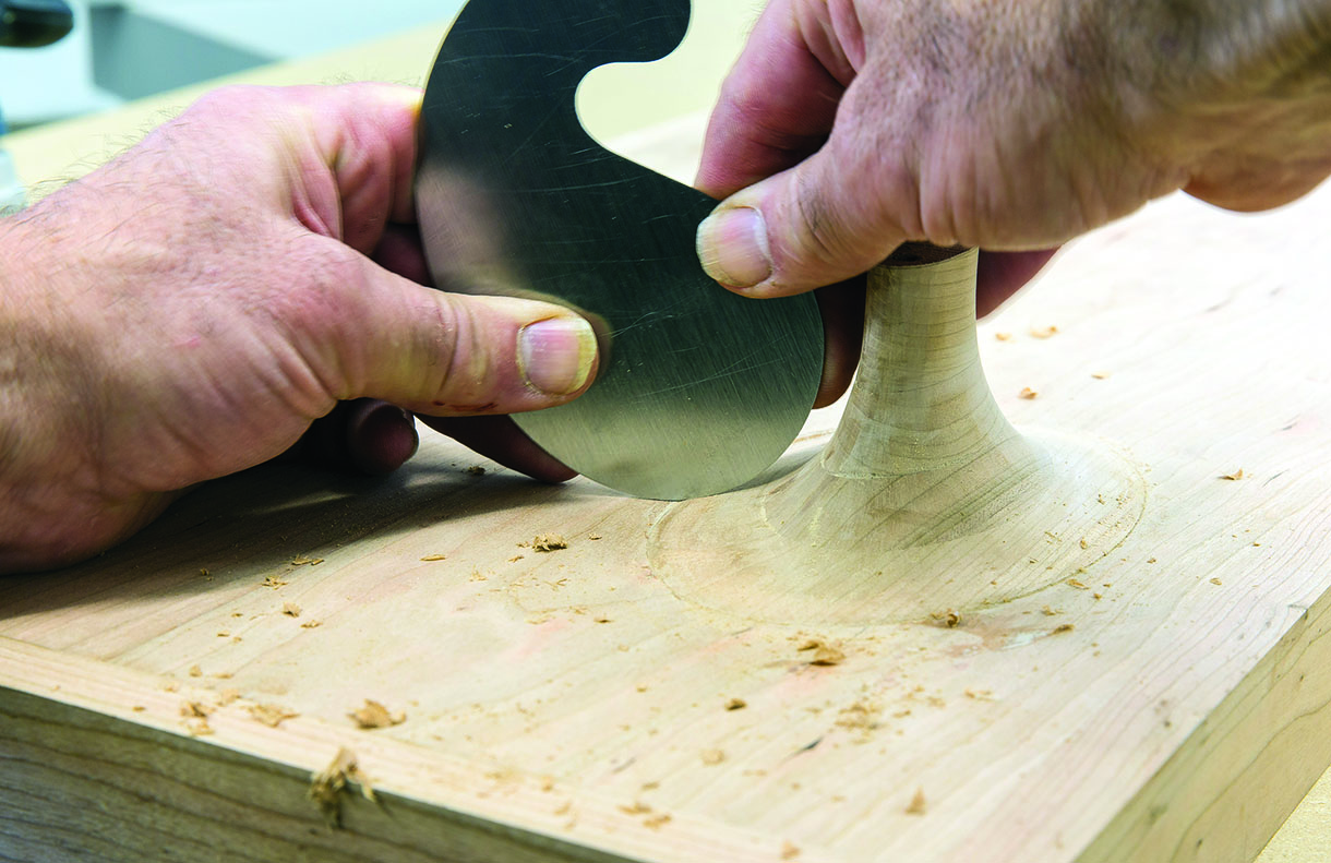
Finishing the interface of an island to table top with a curved scraper
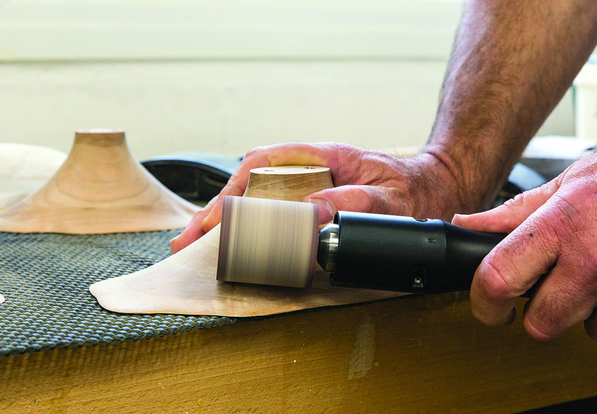
Finish sanding an island top with Kirjes sanding drum
The glass template
The interface between the islands and the glass surface is relatively small requiring good accuracy in setting out their position on a template for the glass supplier. This was achieved by creating angle pieces in MDF for each corner that located the rectangular template in the correct position relative to the top. With the table top inverted a drill could be passed down the reference holes and through the template.
Note: The glass I specified was 8mm toughened. The minimum hole size at this thickness is 8mm. From my experience with this table I would aim for at least 5mm between the edge of hole in the glass and wood edge to avoid visible intrusion.
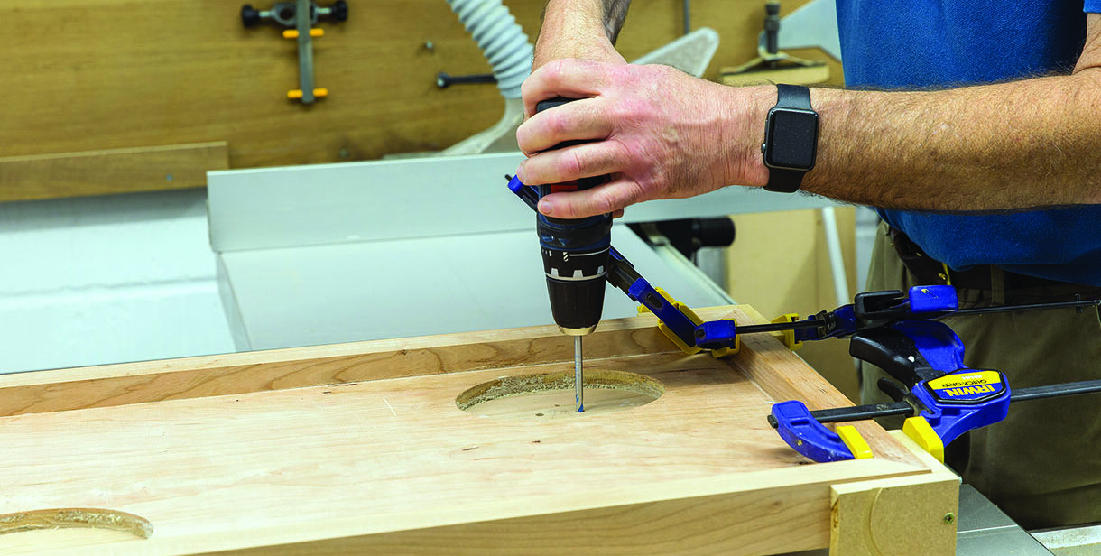
Drilling the glass template through the island reference holes
Legs
The table legs are simple in shape and designed to be sympathetic with the ‘waisting’ of the islands, the feet dimensions being less than at the interface to the table.
As the form of the leg was the same on all four sides a template approach was adopted. First a temporary MDF template was made from three parts biscuited together. The ends were produced by routing a circular segment, which was then parted in the centre and sides squared. Theses ends were then joined to a nice straight centre section. A plywood template, formed on two sides, was then made from the MDF template.
The leg blanks were produced at the maximum section required of 60mm by laminating two 30mm strips together. Ample material was left at both ends to facilitate clamping and handling. The template was then attached by screws to the leg blanks, in waste material areas, and the leg bandsawn to rough shape. The leg was then finished to size on the spindle moulder.
I took some time over deciding on how best to construct the interface to the table top, eventually settling on a fully glued joint based around an integrated glue block. The top of each leg was trimmed to length and scribed against the frame to give the shoulder line for the joint. The leg joints were hand cut, using tenon saws, chisels and shoulder plane and tuned to achieve a precise fit to the frame.
The majority of the finish sanding was carried out before finally parting the lower leg to length as this made it easier to hold the component. A somewhat elaborate clamping set up was concocted to ensure the legs
were glued perpendicularly to the top and pressure exerted in all directions of the joint.
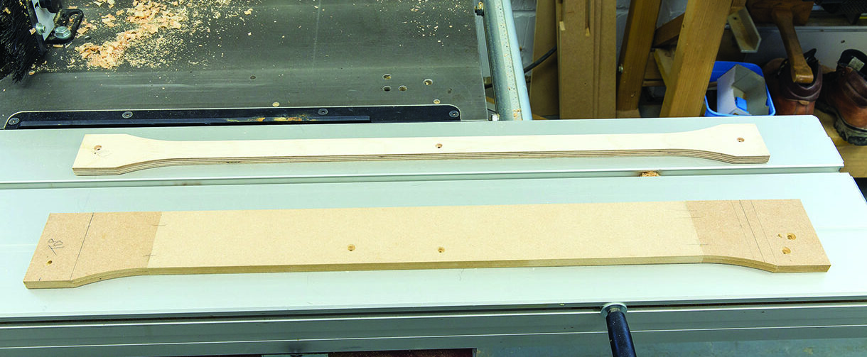
Table leg templates
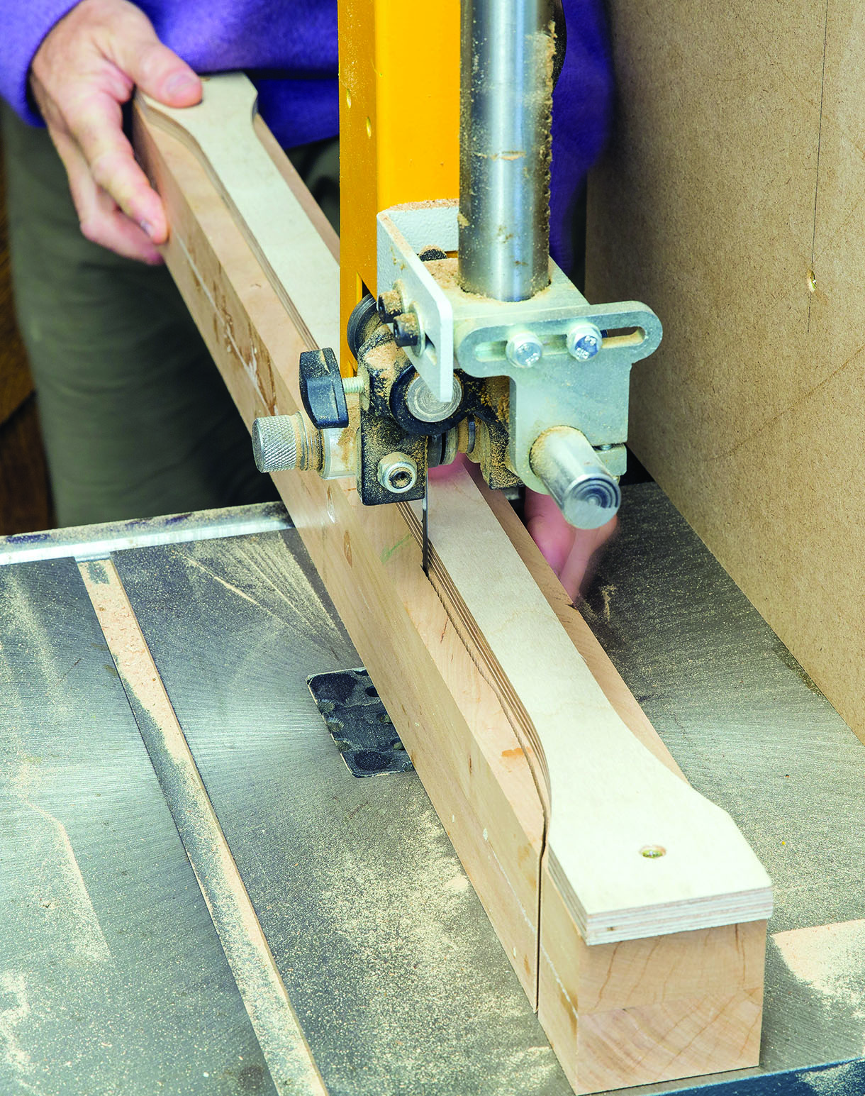
Bandsawing the table legs to rough profile
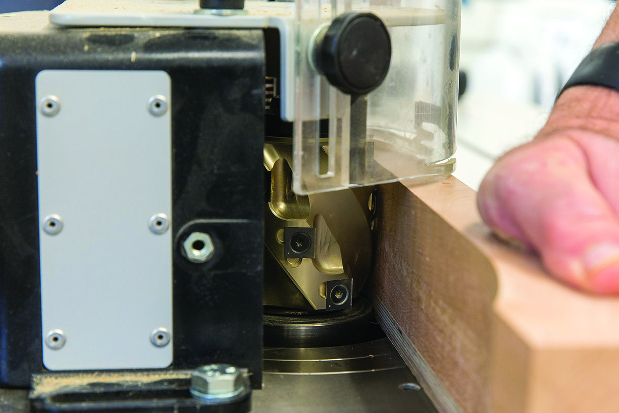
Spindle moulding the table legs to finished profile
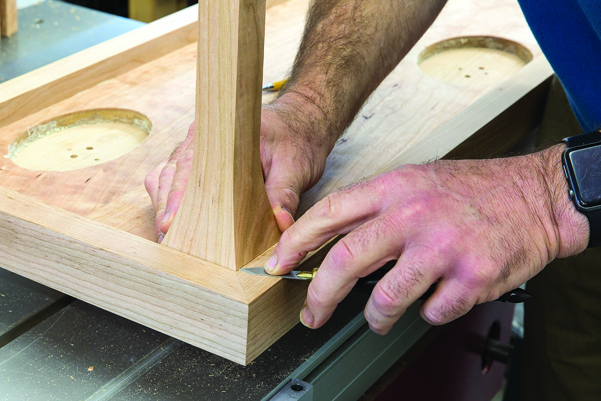
Scribing the top of the leg to the table frame
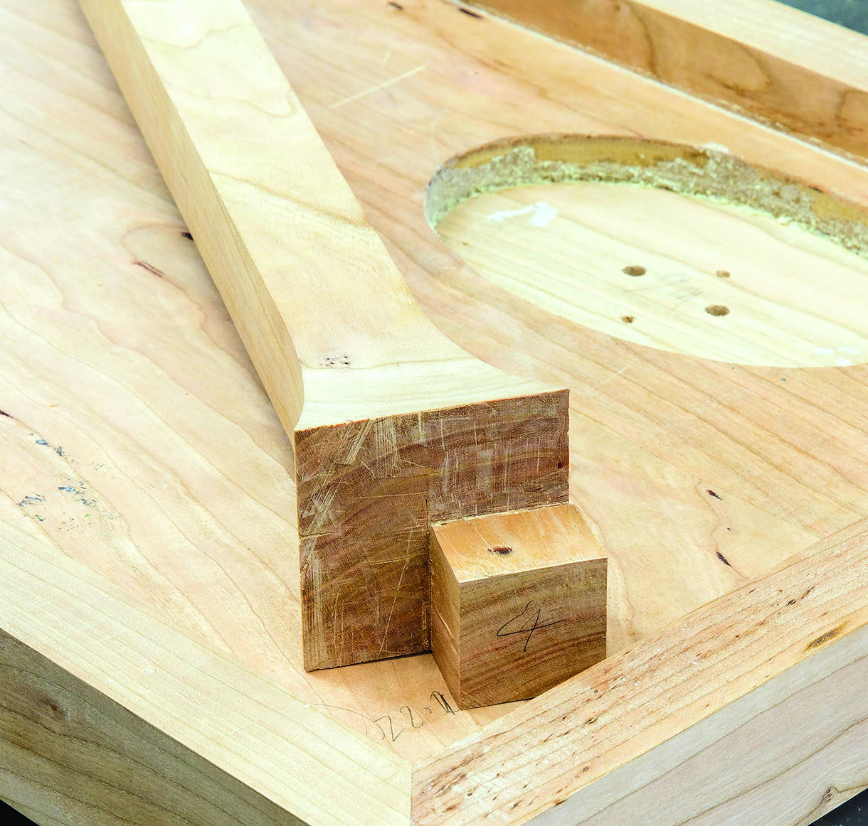
Finished leg joint ready for glueing up
Finishing and assembly
A final inspection and finish sanding of the table parts was made and six coats of Libron Finishing Oil applied to the cherry with a gentle rub down between coats. The glass was then positioned in place and the island tops secured with one dowel and one 100mm screw passing up from under the table.
Overall I am very pleased with the result and am glad that I decided to proceed with the project. Nothing ventured, nothing gained as they say!
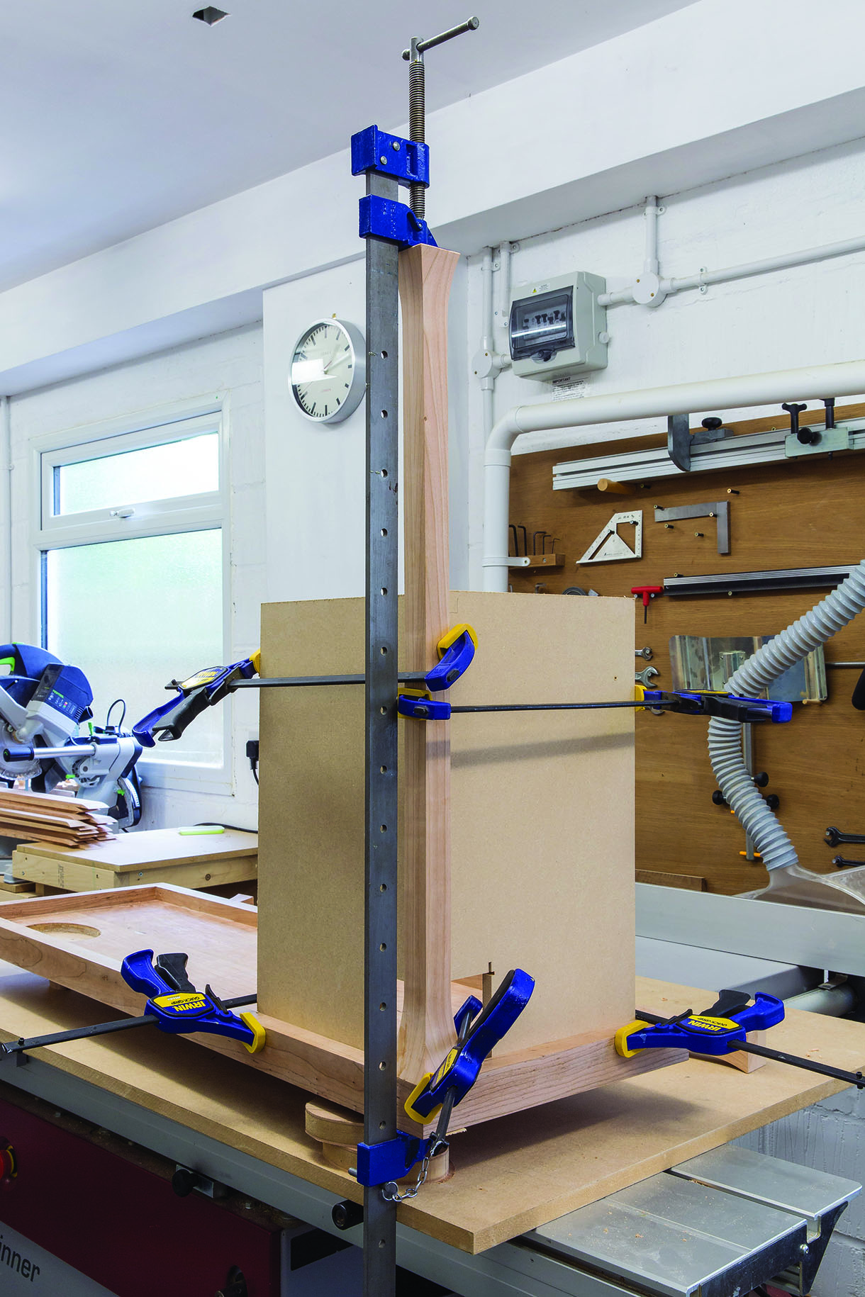
Clamping arrangement for a table leg to ensure perpendicularity


