The Hugo Drinks Cabinet:
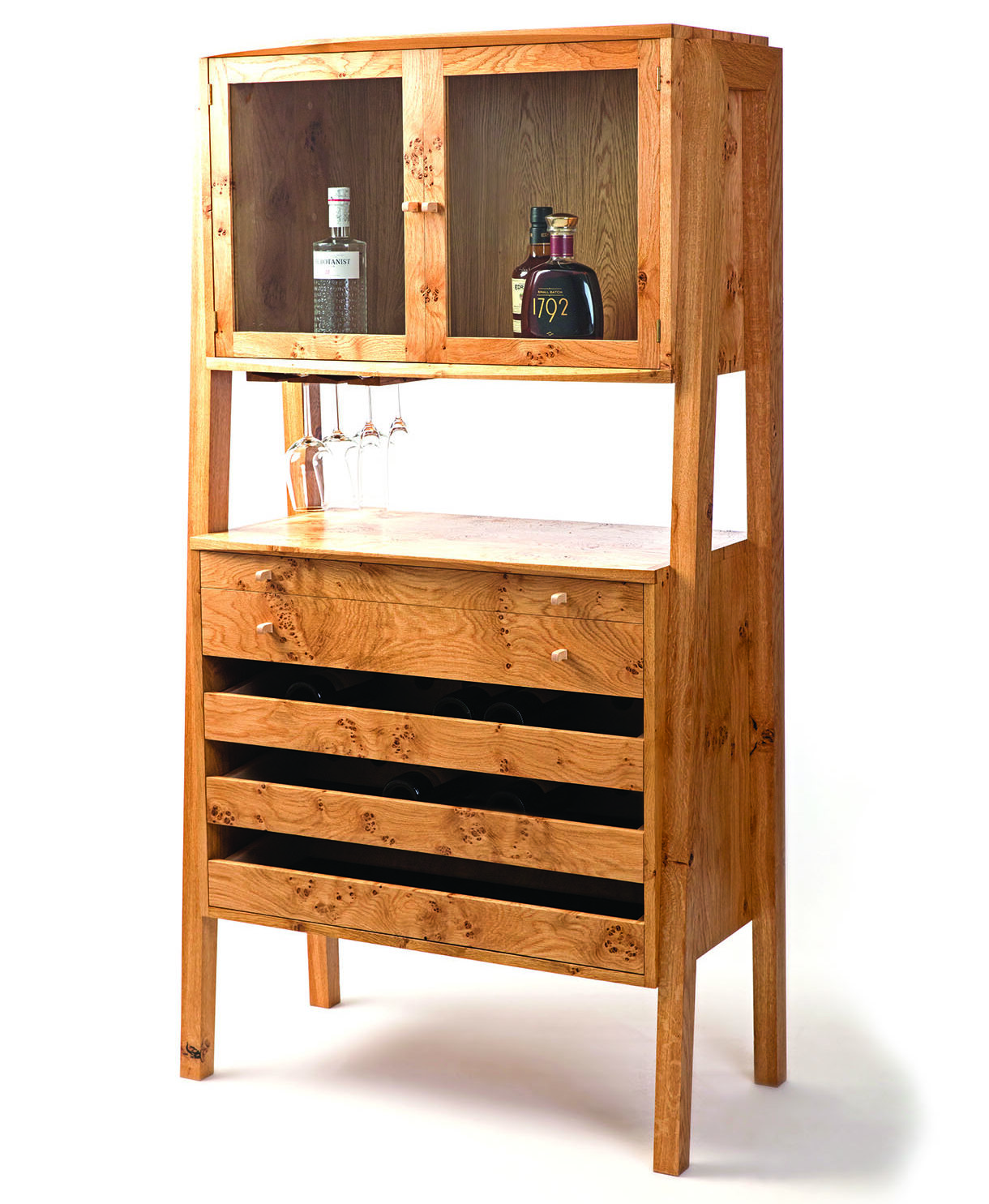
From the height of art deco sophistication and through the mixed up seventies a nicely proportioned drinks cabinet still has style. James Marshall Phillips of Burke & Marshall share their contribution to the art of entertaining.
From the height of art deco sophistication and through the mixed up seventies a nicely proportioned drinks cabinet still has style. James Marshall Phillips of Burke & Marshall share their contribution to the art of entertaining
As luxury items of furniture, drinks cabinets offer designers the opportunity to indulge themselves a little and explore details and features that would seem out of place on more utilitarian pieces. The line between flamboyance and modesty is one that we tread very carefully when designing. Well considered flourishes and detail can turn an otherwise plain piece into something exciting, but too much fanfare can come across as pretentious, noisy and distracting. With this in mind, we set out to design a statement piece that’s not too ostentatious, is highly functional with plenty of space for bottles while also offering a degree of understated luxury.
Burke & Marshall
Burke & Marshall is a handmade furniture partnership between brothers Sam Burke Phillips and James Marshall Phillips. In a modern day world of fast, factory-made disposable furniture they quietly and diligently craft furniture to last. From their workshop in Bedminster they design and make each piece by hand, either as a bespoke solution to a client’s brief or to order as a limited edition from their growing collection of studio designs. They also sell a range of smaller items handcrafted in beautiful timbers for the home in their Casa Curio collection.
Design process
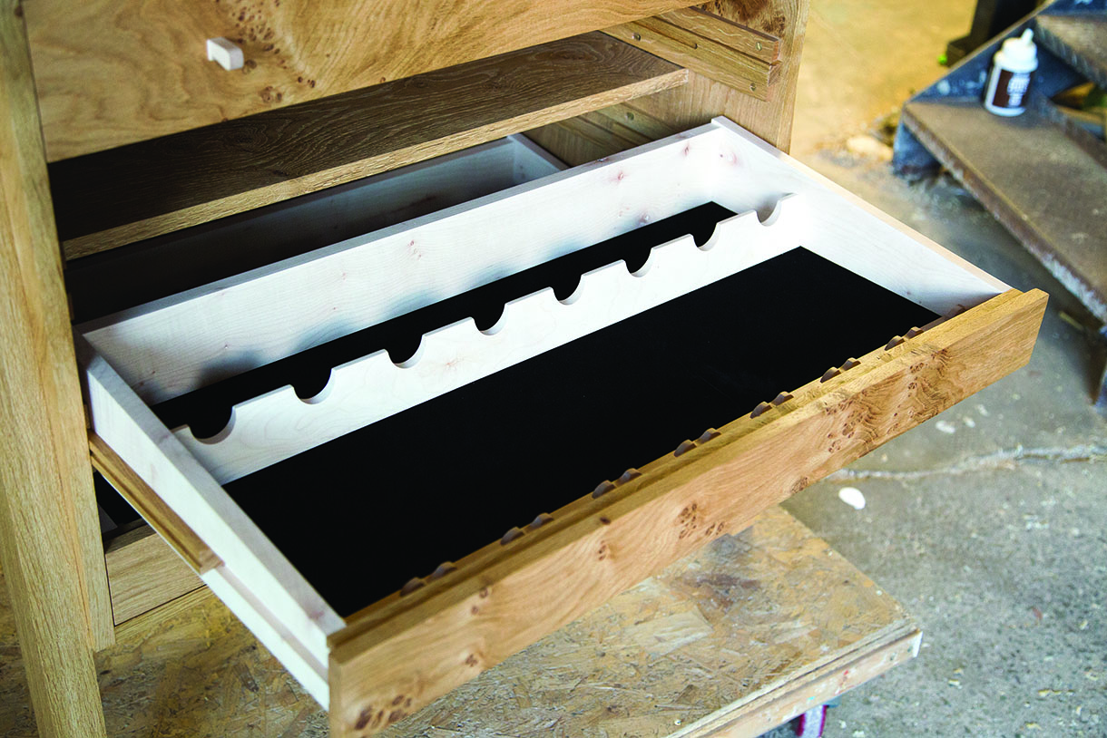
For storing wine bottles I wanted to come up with something a little more special than the standard wine rack and found that drawers offer a great way to store wine. The bottles are kept horizontal so the cork won’t dry out during the ageing process and when it comes to selecting a bottle you can open the drawer to see the labels.
In my initial sketches the top of the bank of drawers would act as a surface on which to prepare drinks but to allow plenty of space for bottles, glasses and arm movement, the spirits cabinet at the top would need to be quite small. With so much variation in the height and shape of spirits bottles this would be inhibitive of functionality, but somewhere to mix drinks was an important feature that I wanted to include. The solution was to add a shelf that slides out from the lower cabinet and a beautiful piece of Welsh slate provides that luxurious element.
The space between the upper and lower carcases is important in the overall form as it lightens the appearance considerably. To prevent this being dead space I adjusted the gap to make it suitable for hanging wine glasses from the underside of the upper carcase.
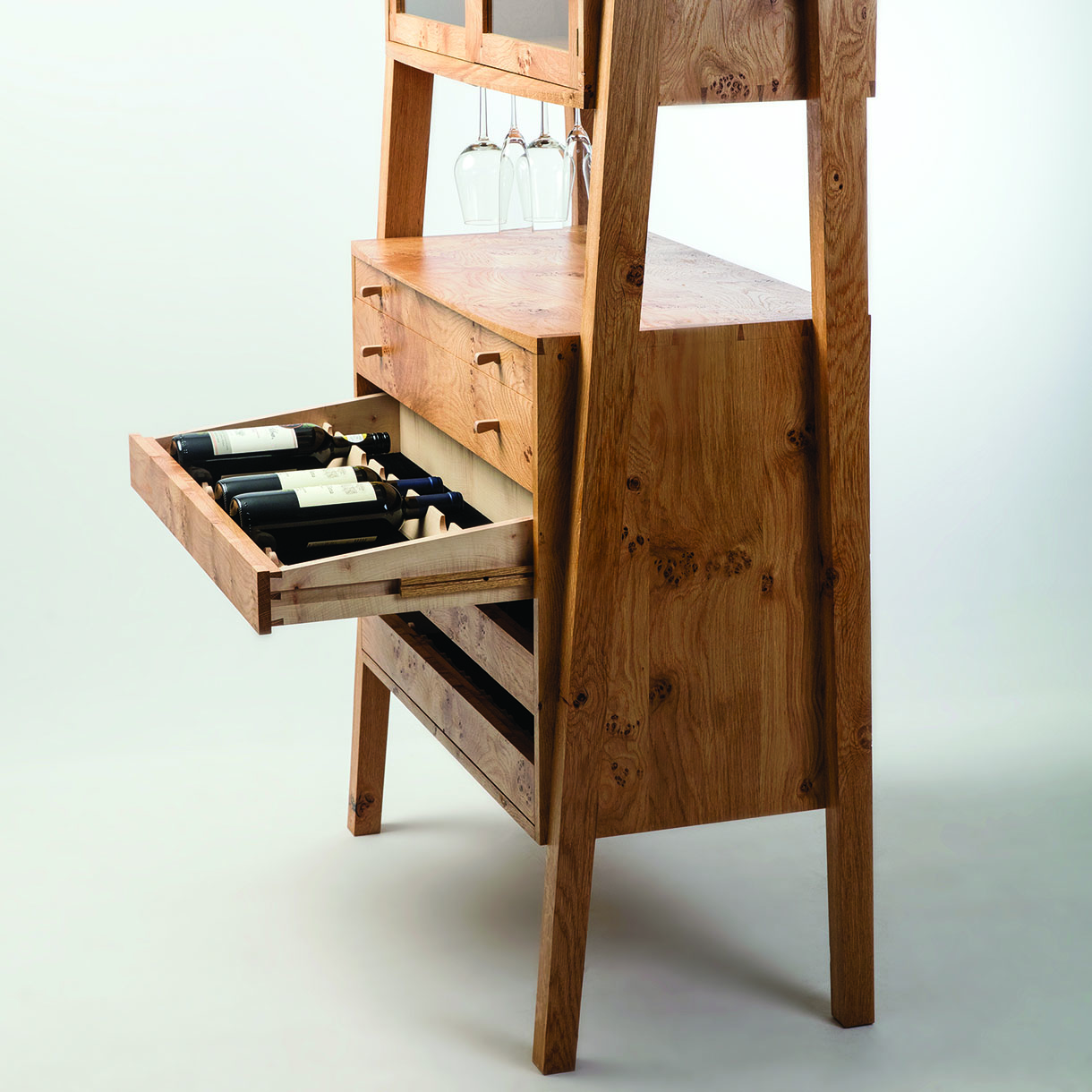
The Hugo cabinet includes a special way to store wine bottles
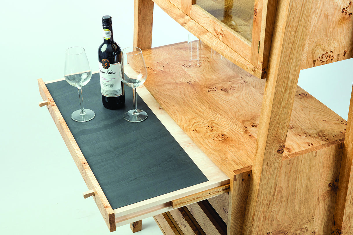
A shelf fitted with a piece of Welsh slate provides a place for mixing drinks
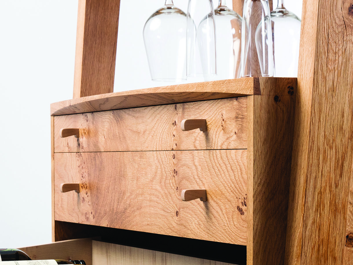
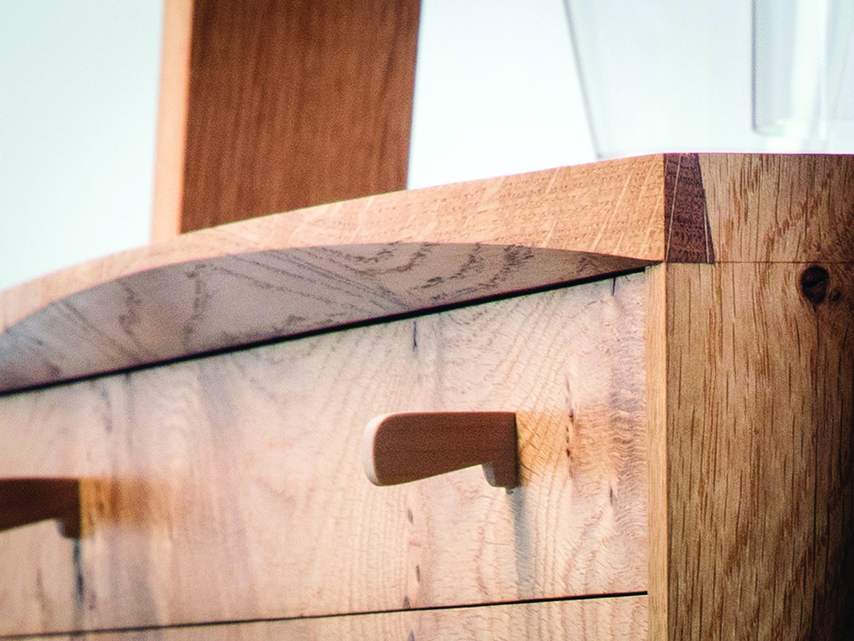
Curved detail on the front edges
Carcase construction
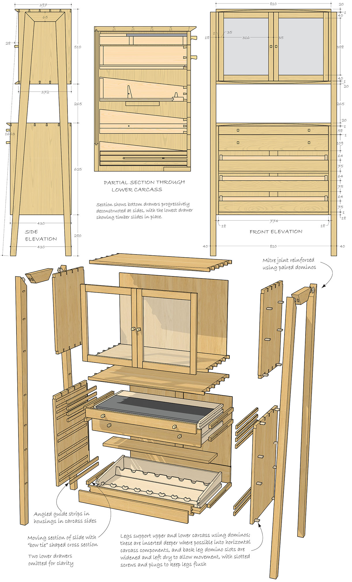
Each panel in the carcases is made up of three boards: three equal width boards in the sides and two equal width boards with a slightly wider board at the front to allow for the curved front on the tops and bottoms. Setting the boards out like this means that the glue lines continue round the carcases.
The shaped detailing on the front edges involves a two-step process. First create an angle along the length of the board and then cut the curve through the angle.
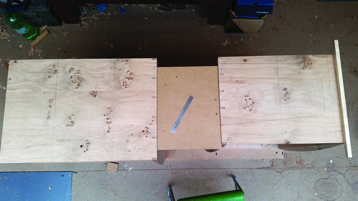
Leave the tops and bottom overwidth. First lay out and cut the pins on the side components. Line up the backs of the components, mark the tails and cut the joinery. Test fit the joint and mark where the front corner of the top needs to meet the side. Joining these two points along the inside face of the component gives you a line to aim for when you come to plane the angle.
Make an MDF template for the curve that is overlength to allow lead in and lead out when flush cutting on the router table. Position the template so that the curve meets the mark at each end, ensuring that it’s centred on the component, and draw the curve on. At this point, if necessary, rip off some of the excess at the front so that the bulge of the curve just about reaches the edge of the panel.
To create the 30° angle along the front, first cut a 45° on the tablesaw (leaving a 4mm flat along the edge) to remove the bulk of material and then use a hand plane with the blade skewed to reduce the angle back to the line. A spindle moulder would make lighter work of this process but we don’t have the floor space at our shop. The actual angle is not critical, just use a sliding bevel and regularly check at a few points to make sure it’s consistent. Stop planing just before your line, to be finished after the curve is finalised. Then draw around the curve template and rough out the curve at the bandsaw.
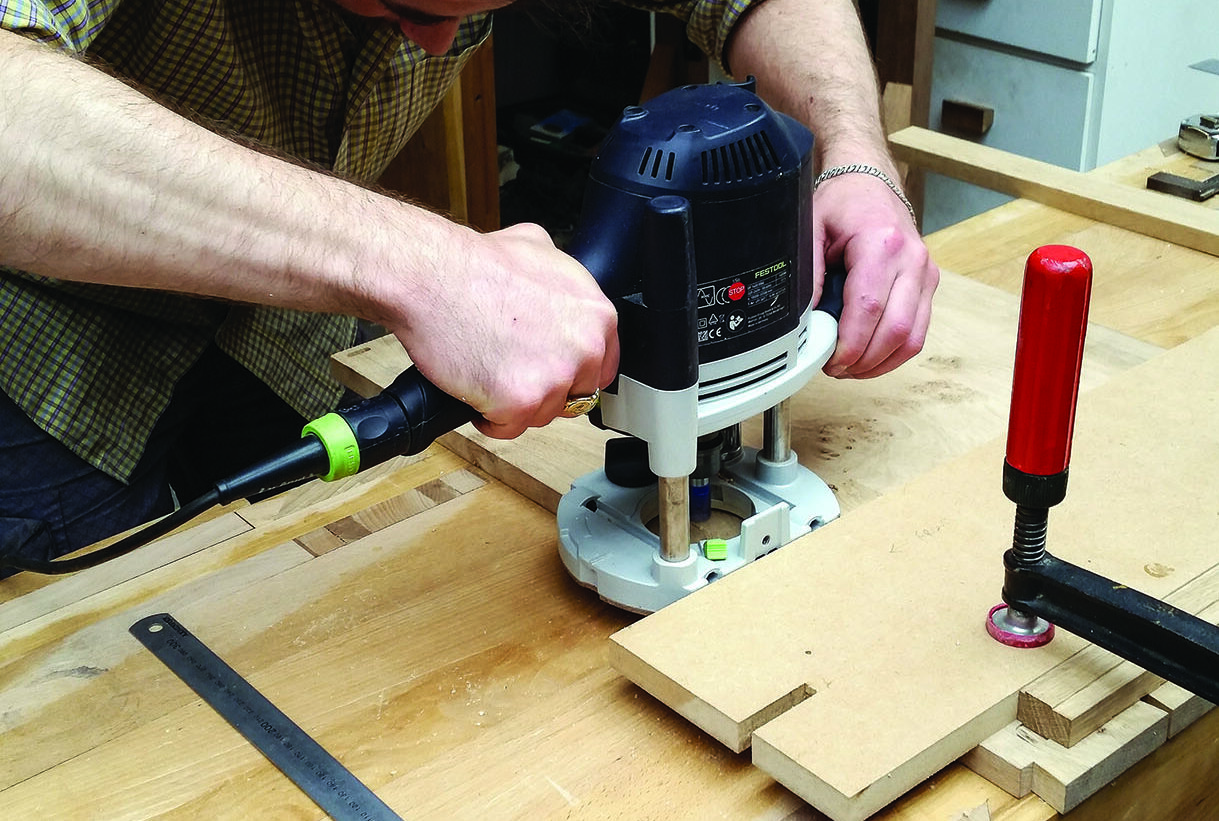
Use carpet tape to fix the curve template onto the cabinet top ready for flush cutting, ensuring that it lines up with your layout lines, erring towards the waste side. You can always fettle the ends of the curve back with a spokeshave or sandpaper if it doesn’t quite match up perfectly.
We flush cut at the router table using a shear trim router bit with bearings at the top and bottom. The shear cut blades leave a good clean finish and the double bearing means that you can always cut with the grain without having to move the template to the other side of the workpiece. Just flip the workpiece over and adjust the height of the cutter.
Reassemble the dovetails and fettle the curve into the corner if necessary until the corner of the side continues up through the top, then disassemble. At this point you have an exact datum to aim for at each end to continue planing until the angled face meets the ends of the curve. We have found this to be a fail-safe way to ensure the three edges converge at the same point.
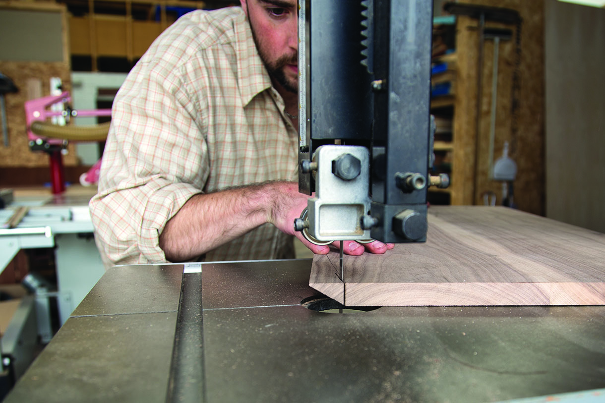
Roughing out the curve
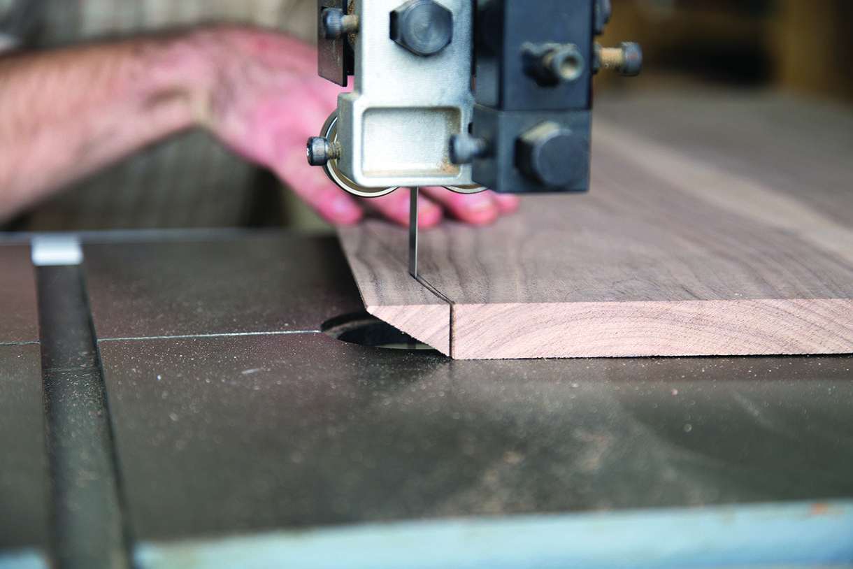
Roughing out the curve
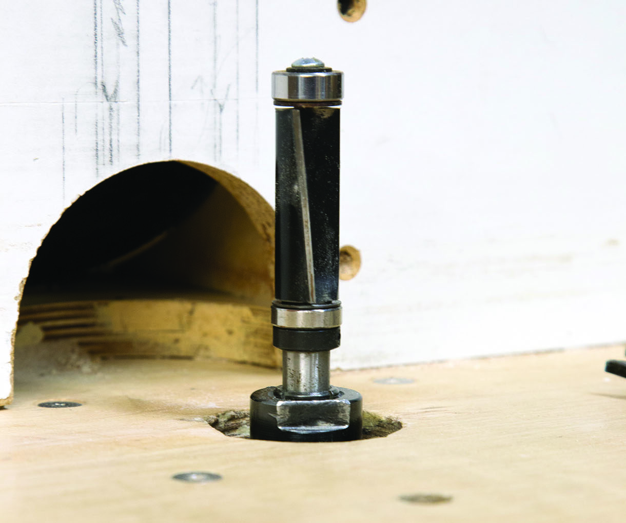
The double bearing flush cut bit
The convergence point
Leg construction
The front and back legs have angles at the tops of approximately 50° and 47.5° respectively and the rail between the front and back leg has a 45° angle at each end. The legs are about 1660mm in length and fractional inaccuracies of angles will be amplified over this distance. As the feet need to end underneath the corners of the carcase the best approach here is to leave the legs well overlength and overwidth too. After cutting the angles, lay the carcases on their sides, lay out a set of legs on top and use a straightedge down the carcase sides to check where the feet will end. With plenty of extra length you can keep adjusting and re-cutting the angles until you’re satisfied with the position of the feet. Save the offcuts from this whole process. They come in very handy as cauls when you come to glue the leg assembly together.
We supported each end grain glue joint with two 10mm Festool Dominoes. As well as significantly increasing the strength of the joint they keep everything in place as the glue dries. Work from the inside of the joint when laying out the Domino mortises. It’s very difficult to tidy up the inside of these joints if the mating faces aren’t properly aligned and it’s pretty straightforward to tidy up the outside, so concentrate on
getting the inside of the corner bang on. Dry assemble the legs and make sure the joints close up nicely. Then mark on the taper for the legs and disassemble. Cut close to your lines at the bandsaw but wait until after glue-up to trim back to the line.
To apply pressure to the joint, clamp the offcuts you saved onto the outside of the piece they were cut from. When these offcuts are oriented correctly they will create parallel faces that you can clamp across to apply pressure perpendicular to the glue line. If the offcuts are too small to clamp directly onto the legs, screw them to lengths of ply to create a surface you can clamp to.
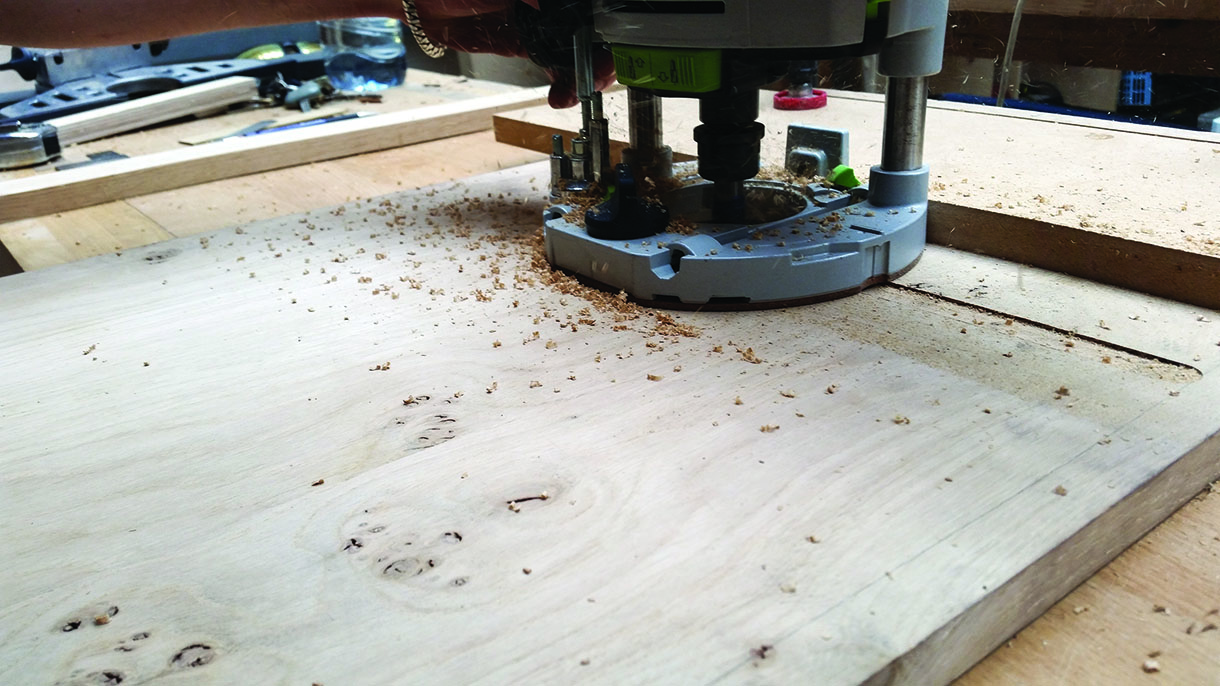
After gluing up, neaten up the taper on the legs. Use double-sided tape to fix a straightedge along your line (we use a long offcut of MDF as a straightedge) and flush cut at the router table. If necessary tidy up the joint with hand planes until all the edges meet up nicely.
When it comes to fixing the legs onto the carcases, allowances need to be made for expansion and contraction. If the carcases can’t move independently of the legs there is a real risk that the mitres on the legs will be forced open as the carcase tries to expand.
The four legs each have seven 10mm Dominoes down their length and the front legs are glued onto the sides of the carcases. Dominoes are glued into the back legs but are left dry in elongated mortises in the carcases so that they can move forward and back with seasonal movement. Use screws to keep the back legs in tight to the sides, through slotted clearance holes to allow for movement. The screw heads in the top cabinet will need hiding so before cutting the clearance holes, drill about halfway into the sides with a 15mm Forstner bit. Cut a load of 15mm plugs from your offcuts and after the legs are glued and screwed in place, pick the ones that best match the colour and grain pattern around the screw and glue the plugs in. Use a flush cut saw to remove the excess plug and then sand or plane over it. If your grain match is a good one most people will not spot the plugs, despite their wide diameter.
Laying out the legs
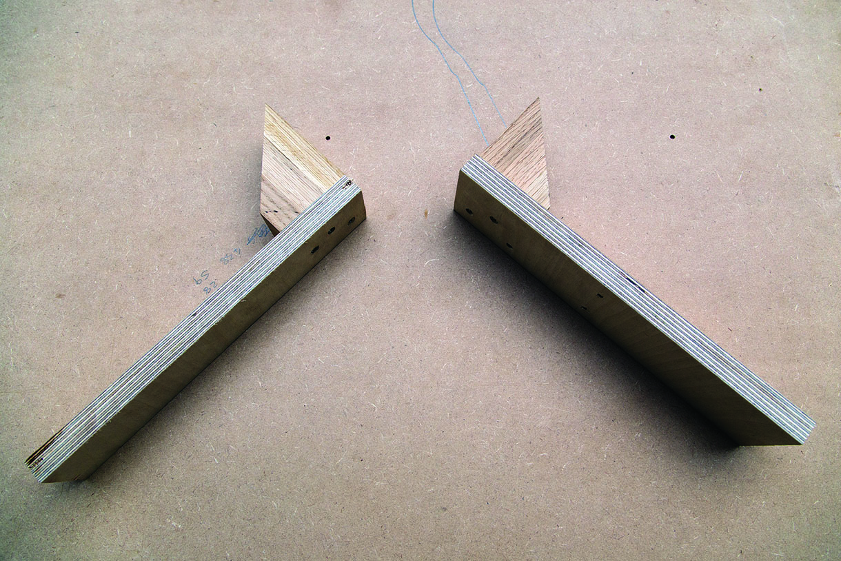
Cauls for the correct clamping angle
Drawer runner system
The drawers move on full extension wooden slides. Here we have used a slight variation on a system developed by New York furniture maker Bob Hare. The tolerances are small with this system, especially with drawers of these dimensions (they are relatively wide compared with their length). If there’s too much play the drawers will rack and bind but a certain amount of seasonal movement needs to be allowed for. It’s a difficult thing to quantify, but the aim is for the housings in the drawer side and the carcase side to be snug around the slide but to move freely with practically no resistance. A couple of coats of well-buffed wax will help with the movement a great deal.
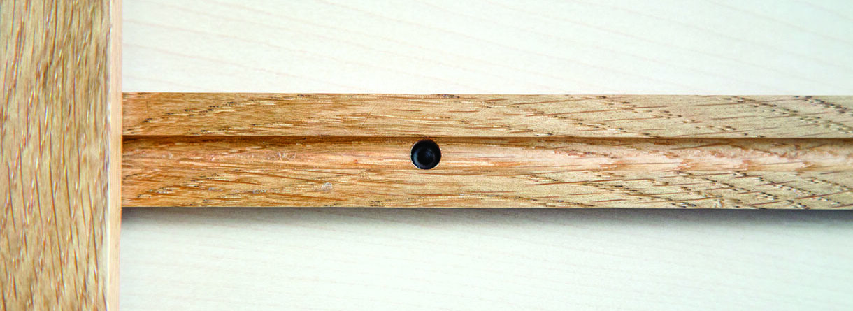
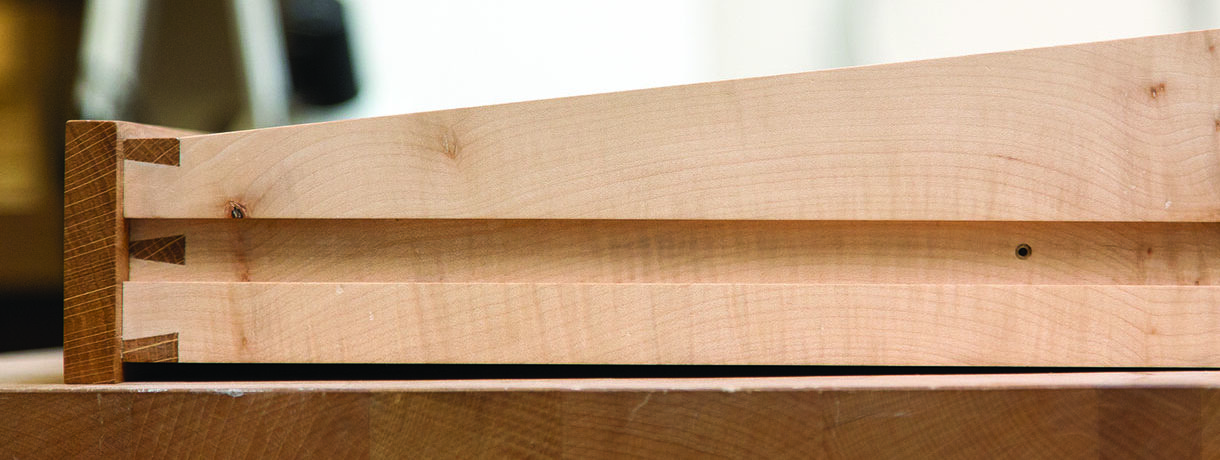
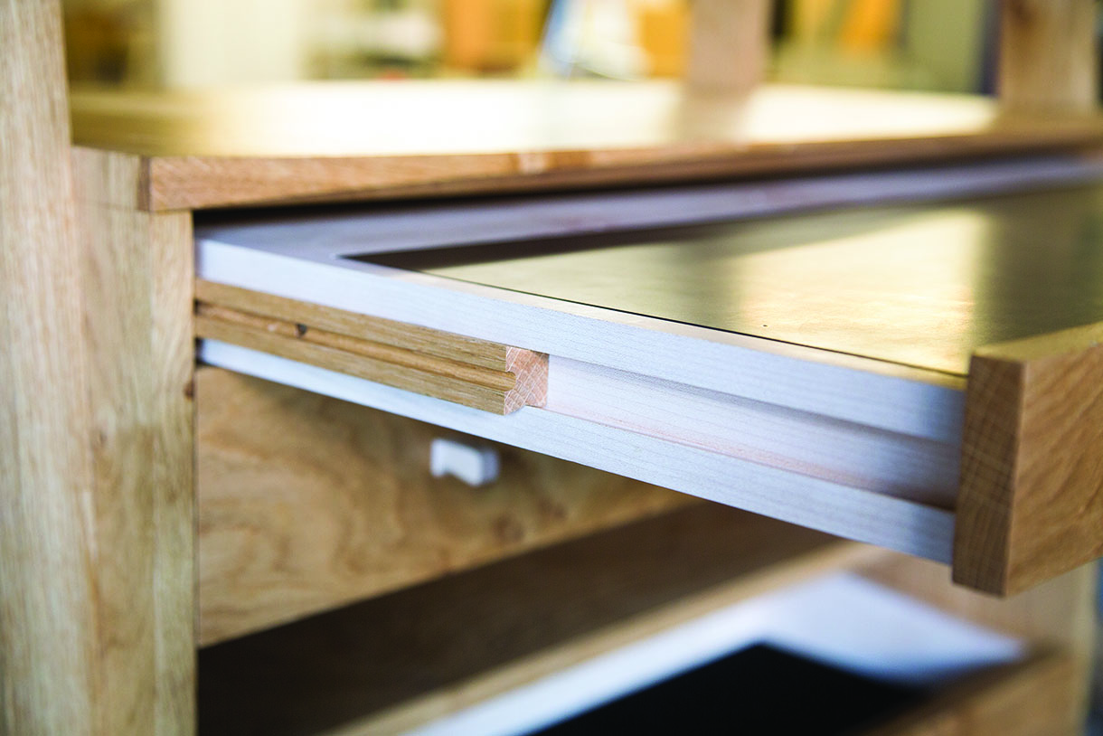
The system works around a free moving slide with a bow-tie shaped cross section. The slide moves in one dovetail housing in the drawer side and in another in the carcase side. Two channels, one routed along either side of the slide, work with machine screws set into the carcase side and drawer side to contain the travel of the drawer.
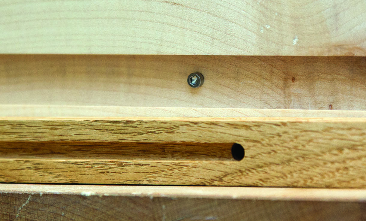
As the drawer is pulled it moves over the slide until the head of the screw in the drawer side contacts the end of the channel. Now as the drawer is pulled further the slides are pulled with it until the end of the stopped channel on the outside of the slide meets the screw head in the carcase side. A brass pin behind each slide prevents them from contacting the back panel as the drawer is closed.
Two holes drilled through the slide at the end of each channel allow access for the machine screws to be screwed into threaded inserts that have been epoxied into the drawer side and carcase. The screws can then be removed if the drawers need to be taken out of the cabinet.
If the drawer fronts were to rest on the front of the carcase when the drawers are closed, the housings for the slides could be routed directly into the carcase sides because the drawer fronts would hide the housing when the drawer is closed. In this design however, the drawer fronts needed to close inside the carcase and so we needed to add angled strips to the inside of the carcase to form the housing. These strips have a small rebate along the top and bottom to form a raised section that sits in a 2mm-deep groove for precision in their positioning and screws hold them in place.
Because it would be difficult to make small adjustments to the distance between the strips in the sides I had to use these as my datum that would define the dimensions of the other components of the system. To this end, the strips dictated the dimensions of the slides and then the housing in the sides was routed to match the slide.
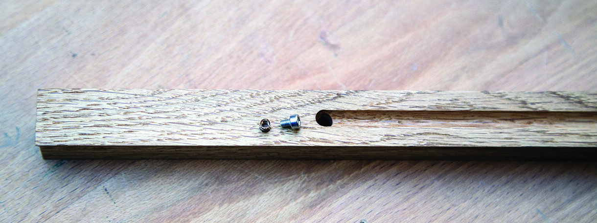
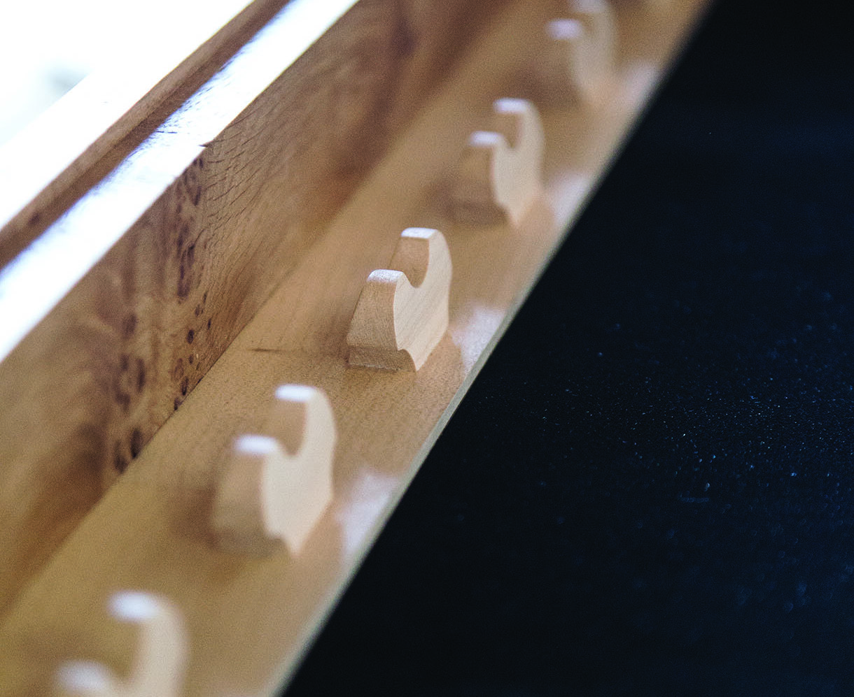
Machine screws are located in the slides to act as either a stop or a hook
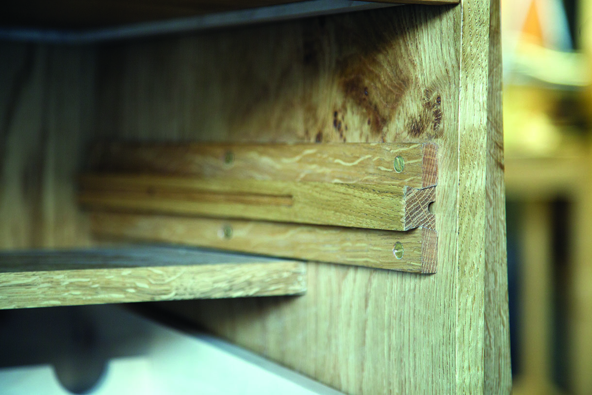
Drawer runners
 The angle on the strips, the shaping of the slides and the housing in the drawer sides are all done with a 14° dovetail cutter at the router table. When cutting the housing in the drawer side you should remove as much material as possible with a straight cutter before angling the sides of the groove out with the dovetail cutter. Precise router set-up throughout is key to successfully using this system so make sure you cut lots of extra strips and slides and have plenty of scrap pieces to use as mock drawer sides.
When making the slides it’s important that the meeting point of the two sloped faces (the point of the V shape on each side) is in the centre of the slide, i.e. set the height of the cutter to half the thickness. If you are left with a tiny wafer of material at the bottom of the V that’s fine, you can remove it with your fingers or a chisel, but make sure you don’t rout higher than halfway. It’s also crucial that the corners of the bow-ties are not touched by the router cutter. The fence on the router table needs to be perfectly aligned with the point at which the cutter emerges from the table, otherwise the slides will turn out lop-sided. It’s likely there will be a small amount of variation between slides and between housings, imperceptible except with test-fitting. Try all your slides in your test housings to get an idea of this variation. If you cut a few extras you can afford to be choosy with their fit. You can glue sandpaper onto shaped offcuts to make specialised sanding blocks if you find any of the pairings have tight spots.
If you have a go at making drawer slides like this I’d highly recommend that you make an accurate mock-up before taking to your carcase or drawers with a router!
Routing the grooves for the dovetail strips
The wine drawer
 There are some excellent quality metal concealed drawer runners on the market that have a smooth, easy motion. However, you can always hear bearings moving when you open them and if you peer inside the cabinet you’ll see ugly mechanisms screwed to the sides. They have their place and we have used them often in other furniture, but there’s something very rewarding in making slides like this. The motion is pleasing and it’s accompanied by a very satisfying succession of clunks and knocks as the wood contacts the screw heads and brass pins. It’s a feature that’s not immediately apparent but will be appreciated every time a drawer is opened, an inconspicuous touch that brings a sense of luxury to a functional piece.


