Wall-Mounted Workbench
Walter Hall makes makes the best use of space in a workshop reorganisation
Walter Hall makes makes the best use of space in a workshop reorganisation
Lately, I have been reorganising my workshop and for a number of reasons, I needed to move my lathe away from the wall so that I could have better access all around it. I also needed to find a better storage place for my scaffolding tower. Because of the location of brick piers, boilers, pipework, etc. there was only one stretch of wall where all parts of the tower could be stored together. Fortunately, this was the same wall from which the lathe was going to be removed. However, I cannot afford to waste this much wall space on storage alone, so I decided to build a workbench over the storage area. The only other design criterion was that this project must be completed quickly so that I could get on with other work. As it turned out it was completed in an afternoon (including a trip to the builders’ merchant for the timber and shield anchors).
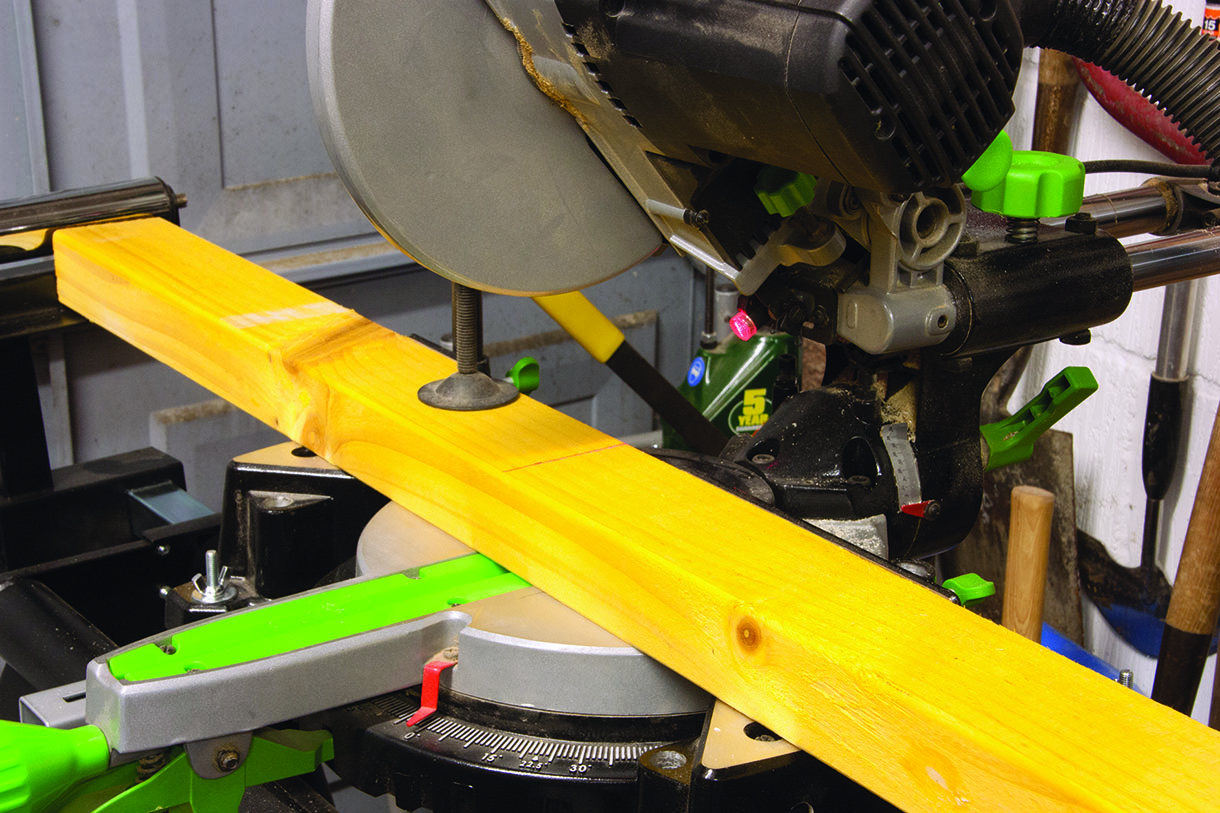
The chopsaw proved invaluable for fast and accurate repeat cutting to length
Defining the problem
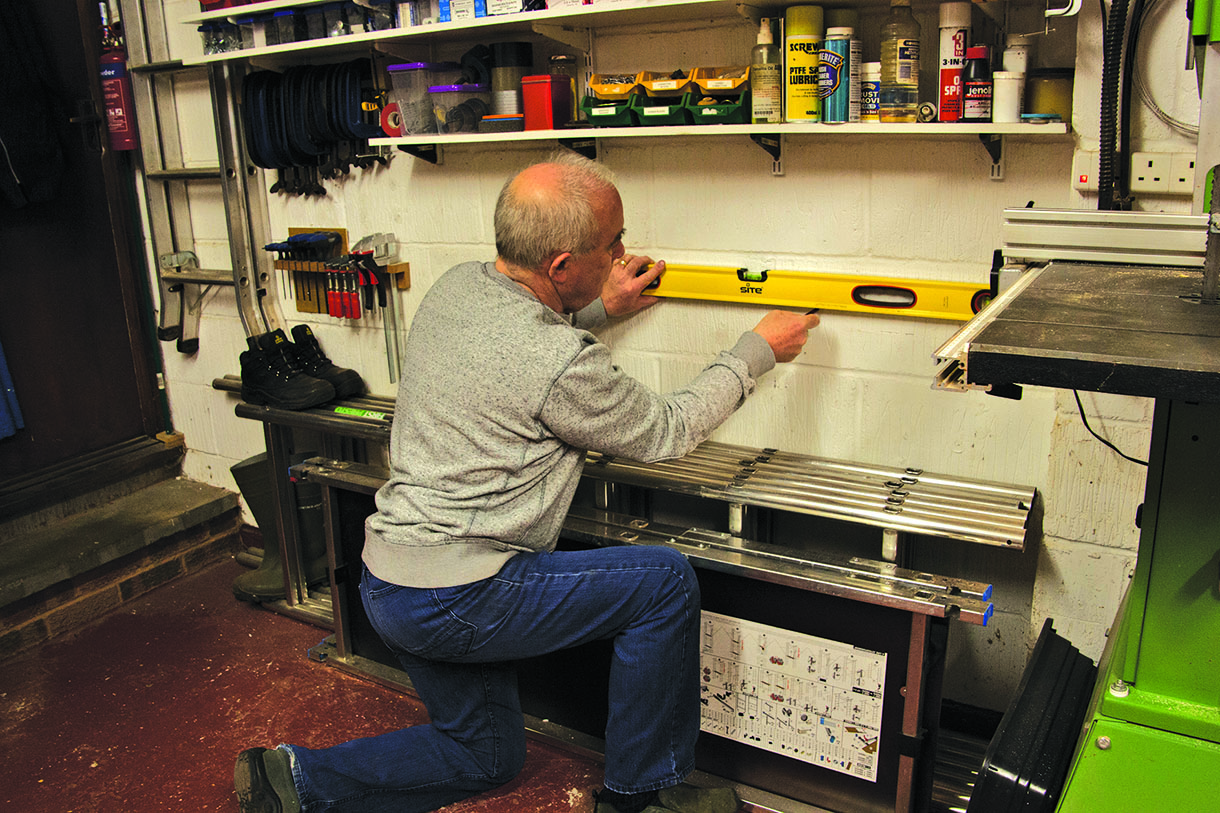
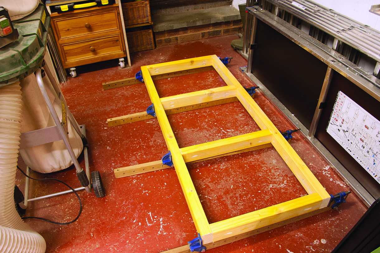
As you can see from the photograph, the bench needed to be supported between the wall and the frame or legs that supported the front, as the tower stored underneath precluded the installation of any cross bracing or rear legs. It also needed to be high enough to allow clearance for the tower components to be accessed by lifting them over the step to the left of the photograph.
Choosing materials
The need to be self-supporting called for a robust wooden frame, so I decided to use 45 x 68mm Canadian Lumber Standard (CLS) timber of the kind generally used by builders for roofing members, joists and other load bearing structures. The first job was to cut the sections to length on the mitre saw.
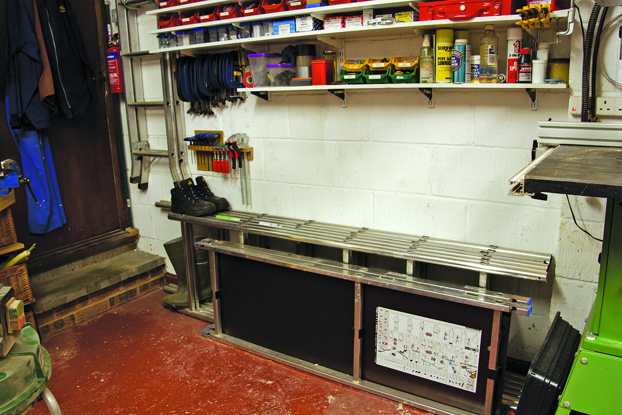
The slightly awkward space into which Walter wanted to fit the bench
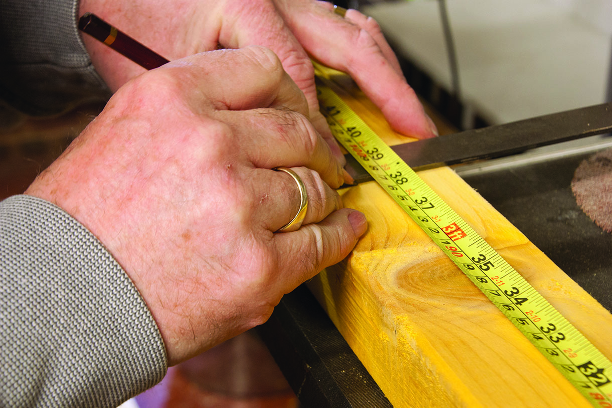
Measuring, cutting and joint making
The mitre saw end stop was used to ensure that all of the cross members were exactly the same length. This is not fine cabinet work, nonetheless square joints and a true frame are essential if problems are not to be encountered on assembly or installation. The positions of the joints on the front frame member were carefully measured and marked out with a tape and engineers square to enable correct positioning of the
cross members.
Once the front was marked out the measurements were transferred to the rear frame member using the square. This is a much more accurate way of ensuring the positions are identical on both work pieces than measuring and marking separately. The prepared components were laid out on the floor to check for fit and square before moving on to the next stage of the work. It is better to correct any errors at this point than try to adjust after assembly.
For a combination of speed and strength I used pocket hole joinery, with two screws from one side and one from the other forming a ‘dovetail’ arrangement that is almost impossible to pull apart once assembled. My pocket-hole jig was clamped to the bench and connected to the dust extractor and all of the joints prepared in one session.
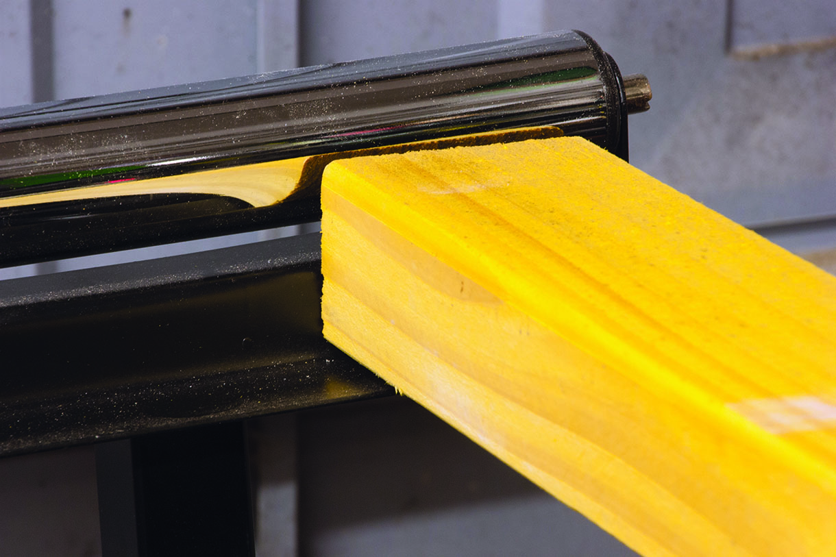
I used the roller stand as a convenient length stop each time
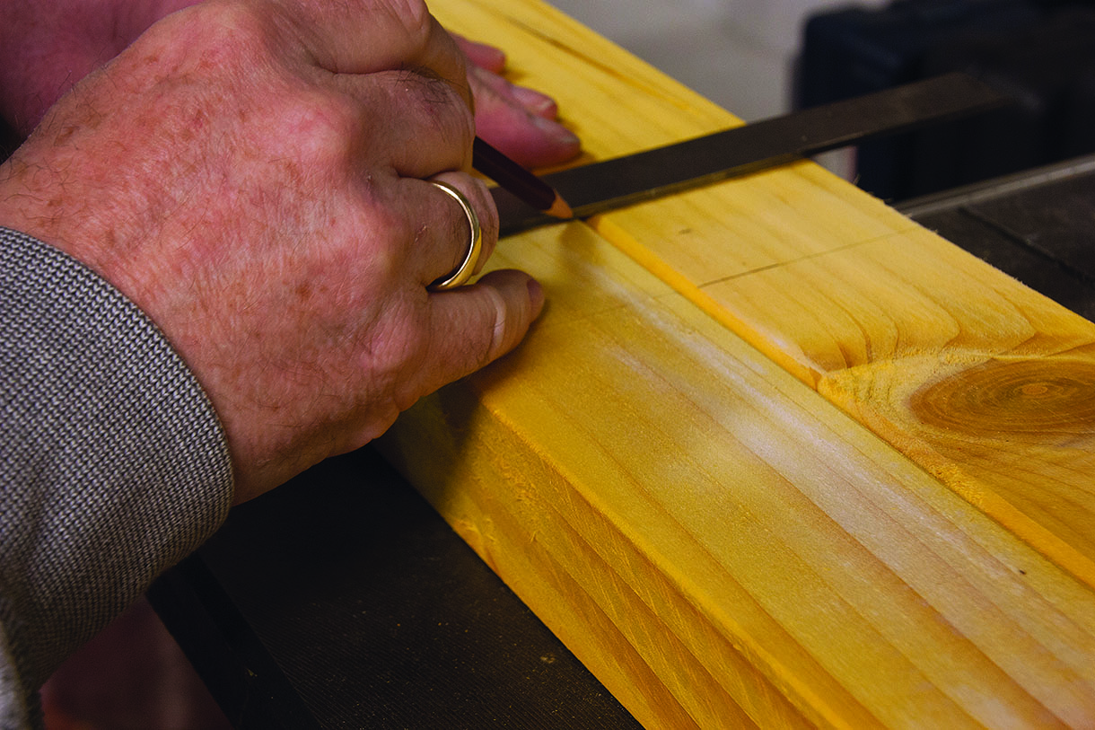
All same-length measurements were transferred across to the other rail
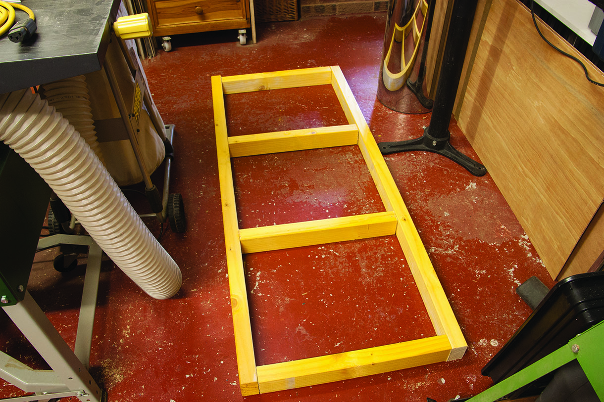
Then the frame was laid on the floor to make sure it would go together neatly
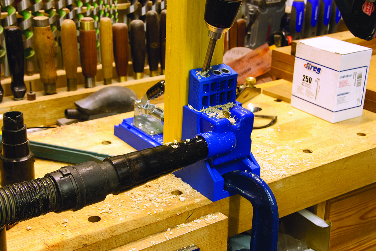
The set-up needed proper extraction to keep the job clear of chippings
Wall fixing
The next stage was to prepare and drill the wall for the 10 x 140mm shield anchors that were to be used to attach the frame. This is much easier to do from the single rear frame member than trying to measure from an assembled frame. The first step was to mark a level baseline on the wall in line with the proposed position of the bottom of the framework. Don’t rely on the accuracy of the brickwork or blockwork for this.
I screwed temporary plywood support blocks below the line to support the frame while marking out. This makes it easier to support the timber frame member with one hand while drilling a pilot hole with the other.
The positions of the 10mm holes for the bolts were marked out and drilled on the pillar drill for accuracy thus helping to ensure a level structure. Position the holes carefully to avoid them coinciding with the cross members. I used five shield anchors. Frame fixings or fewer anchors might have been adequate here, but I wanted this to be a robust structure capable of withstanding some light hammering and metalwork.
Holding the frame member against the wall, supported by the temporary plywood blocks, I used a 10mm masonry drill to drill a pilot hole marking the position for each anchor. I didn’t really need an SDS Hammer drill to drill these soft blocks but the only 16mm masonry drill I had was an SDS fitting so I just turned off the hammer facility and drilled the holes in rotary only mode. I took care to ensure I was drilling square to the wall and level.
I blew out the holes in accordance with the instructions for installing the shield anchors. I used an airline and blowgun (I always use a dust mask for jobs like this because a lot of dust is created during this process and I really don’t want my lungs full of brick or concrete dust).
Marking up the wall, avoiding the mortar line so the bolts would anchor properly
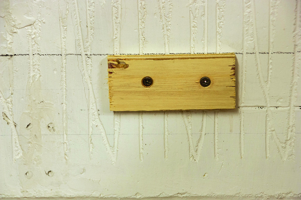
Temporary support blocks were used to rest the frame on for pilot hole drilling
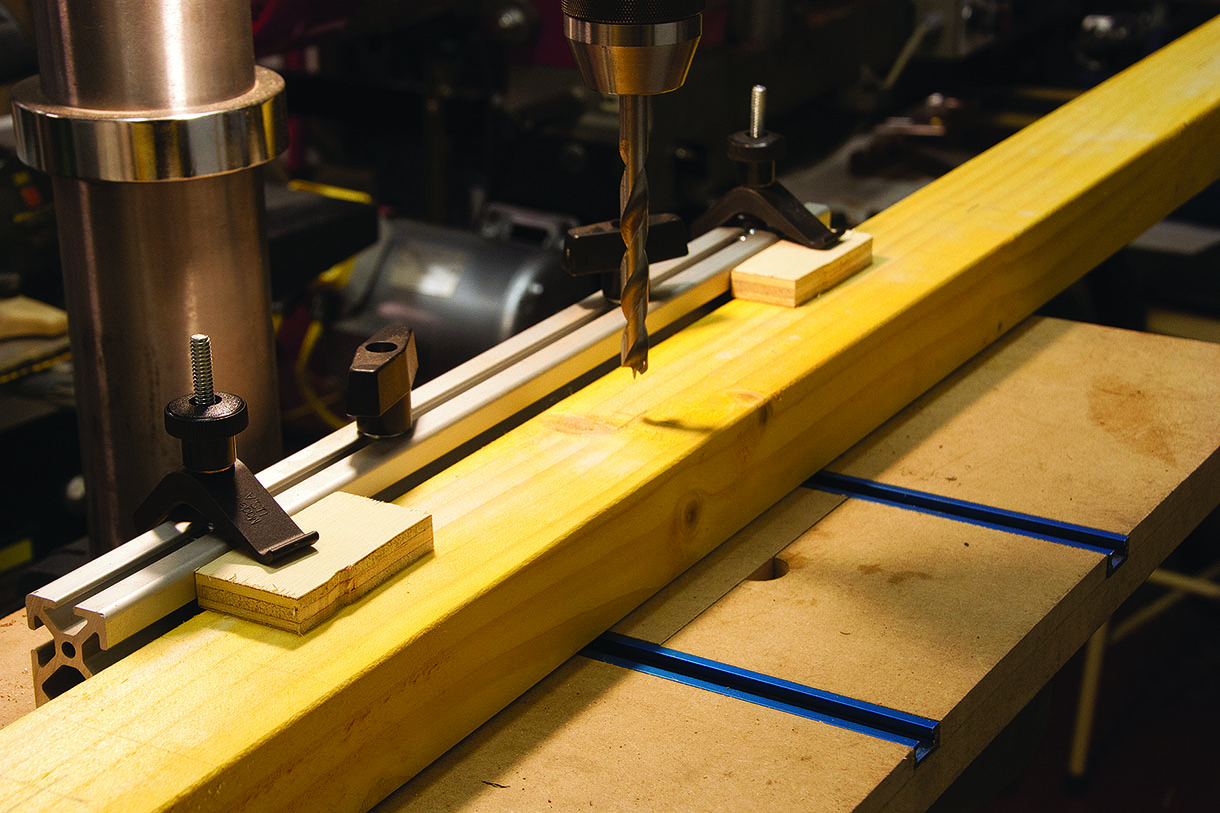
For accuracy and neatness I drilled the holes using my pillar drill
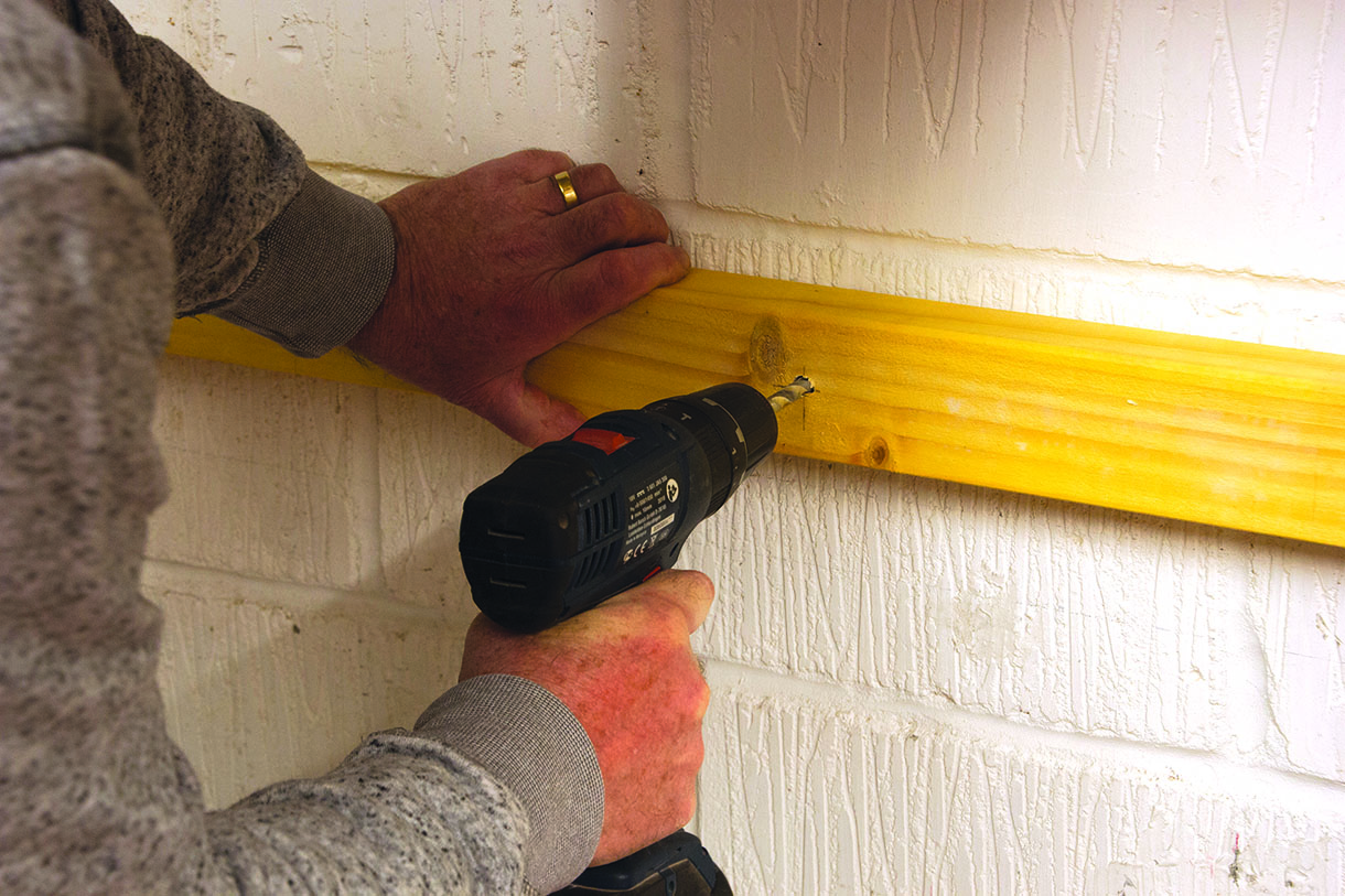
Then I used a masonry bit to drill and mark the blockwork through the wood
Frame assembly
Now that the wall was prepared the frame could be assembled. I clamped it up square and true before screwing together with the pocket-hole screws. I think the best way to install shield anchors is to assemble them through the frame, lightly entering the threaded section of the anchor onto the bolt, then once all the anchors are in position assembling the whole structure to the wall. I find this much easier than inserting the anchors into the holes first then trying to thread the bolts in through the wooden framework.
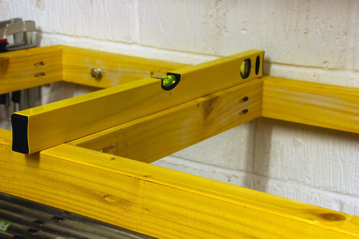
I used a pair of roller stands to support the front of the frame while inserting the anchors into the pre-drilled holes. Before tightening the anchors I checked carefully for level across the frame, adjusting the roller stands as necessary. I made sure everything was level laterally and at right angles to the wall.
Once everything was in position the shield anchors were tightened. I used a socket and ratchet driver for this they take quite a lot of winding in and it can be laborious work with a flat or ring spanner. Tighten until the frame is solidly attached to the wall but do not overtighten the bolts to the extent that the timber is crushed.
Once the bolts were tightened the installation was actually strong enough to support itself but in order to ensure everything remained level I left the roller stands in place while measuring for the front legs against the frame. Each leg was measured individually as my concrete workshop floor is not very level. Once cut to length the legs were pre-drilled for four 75mm woodscrews and attached to the rear of the front frame member. The frame structure was completed by screwing a bracing member across the lower part of the legs to prevent any sideways movement. I considered using brackets to bolt the legs to the floor but by this stage the structure was so robust as to render this idea completely unnecessary.
To avoid wasting the space above the stored tower and below the bench I installed a single shelf using twin slot shelving supports and u-brackets. Note that this only extends part way so that the tower components stored underneath can be slid forward of the shelf then lifted over the step for access.
Offcuts of the framing timber were used to make screw blocks to attach the top. These were pre drilled in both directions and attached to the frame. Much though I would have like a solid beech or oak worktop this would be have been expensive overkill for a utility bench so I used 18mm MDF.
The project was completed by mounting a No2 engineer’s vice using 8mm setscrews. A couple of coats of hard wax oil will protect the MDF surface from excessive staining.
The frame was clamped up square and the pocket screws driven in
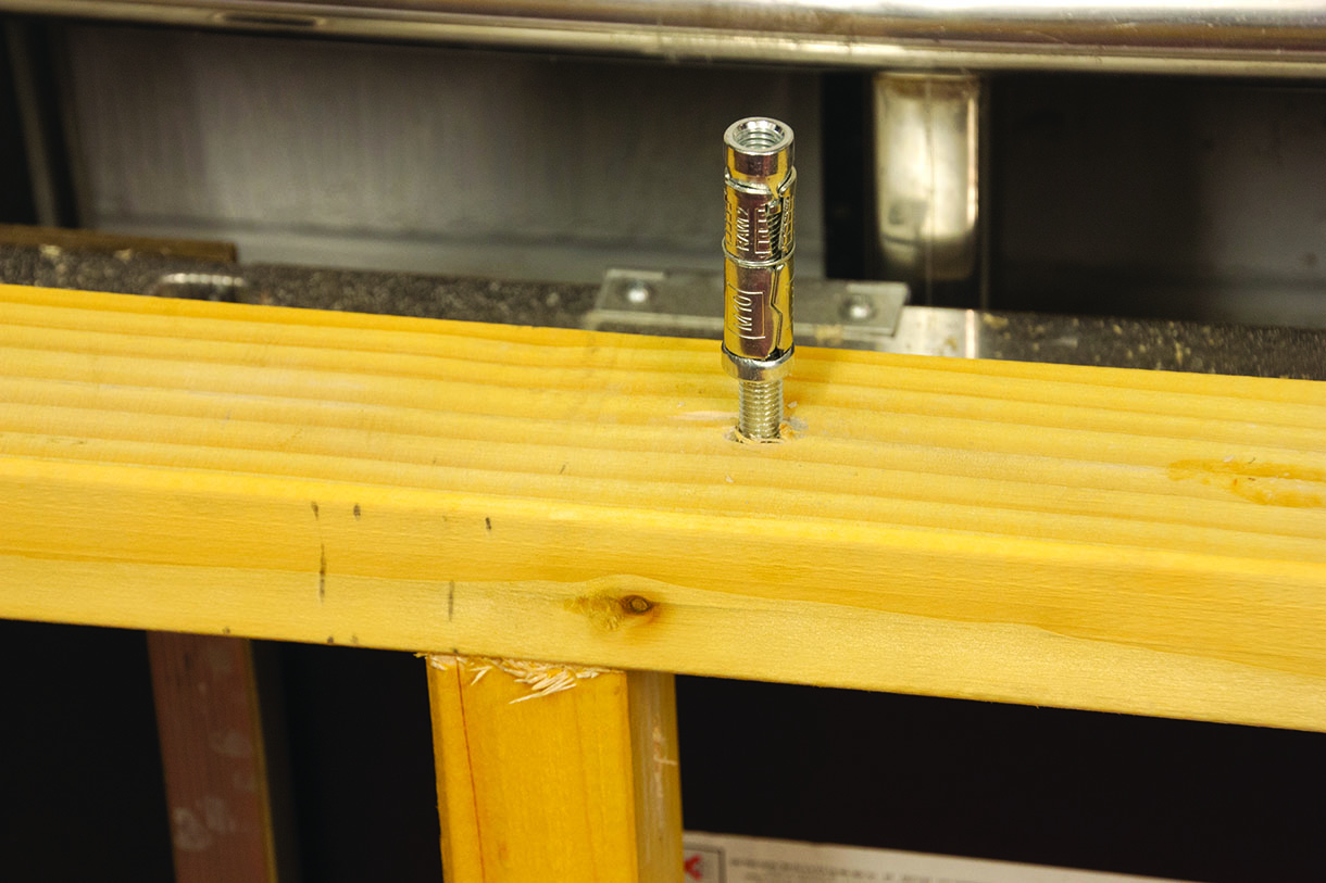
All the anchors were pre-installed in a line ready to push home in the blockwork
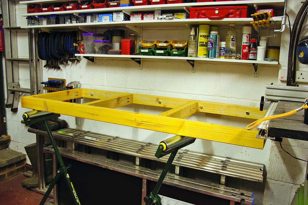
Two roller stands kept the frame level during wall fixing
Two roller stands kept the frame level during wall fixing
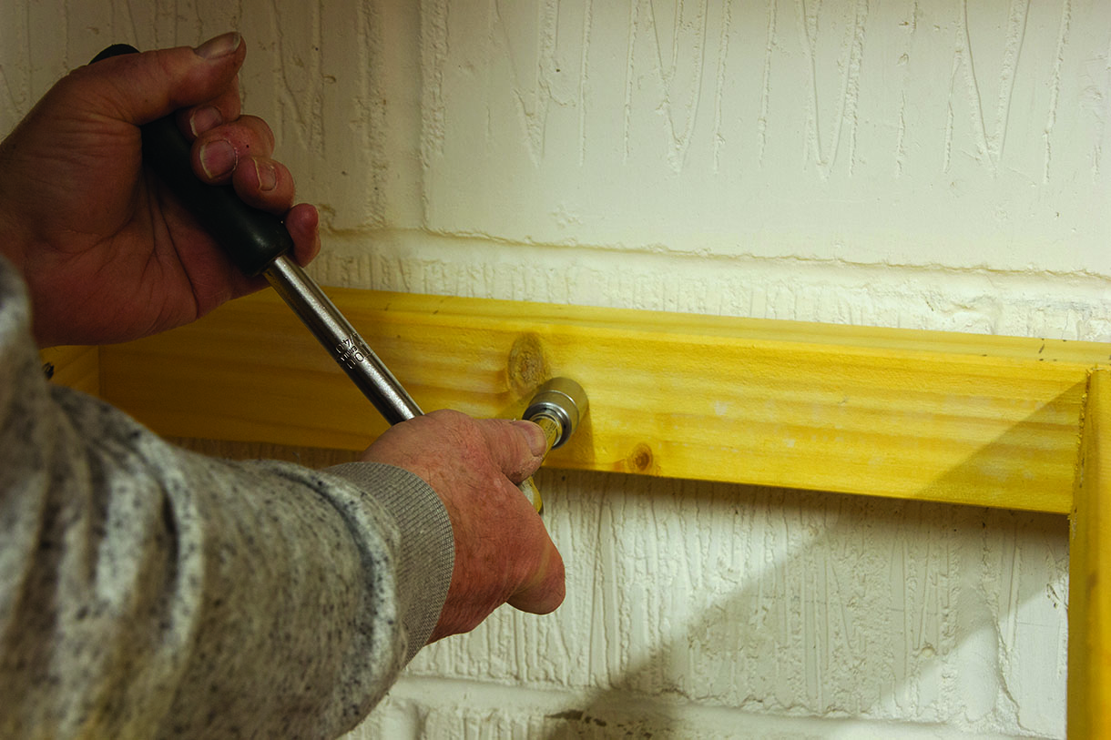
Using a ratchet wrench and a socket of the correct size to tighten the anchors
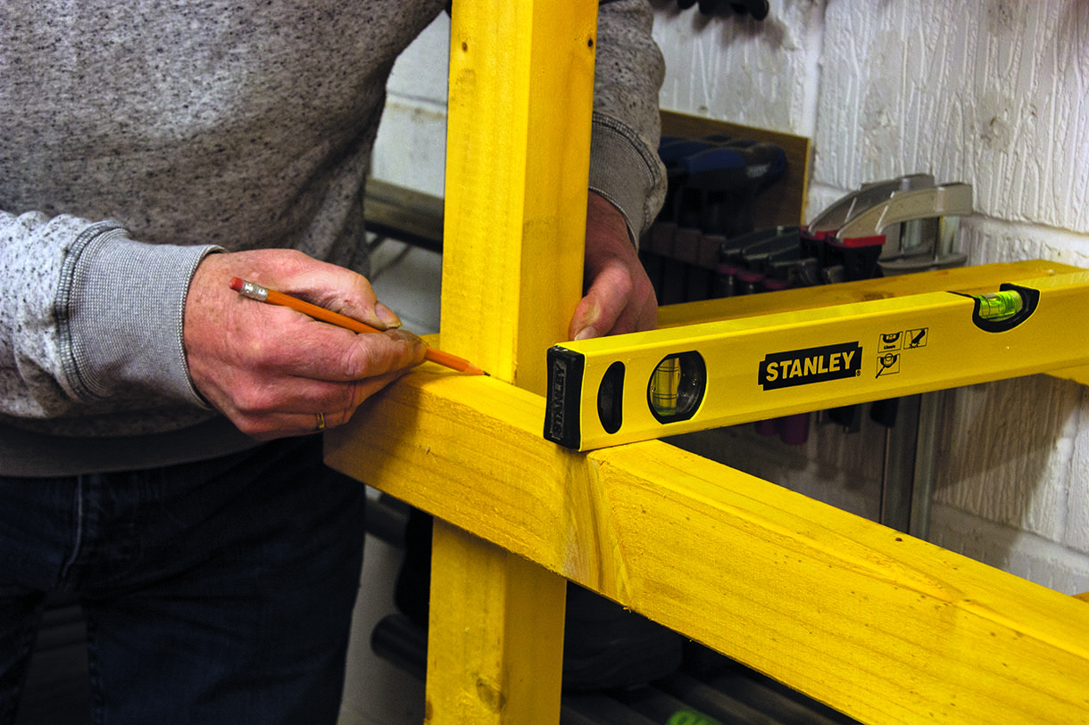
Marking the legs for each position taking account of floor variation
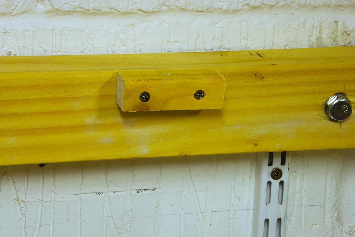
Blocks were screwed on for fixing the top down with vertical screw going up through each one
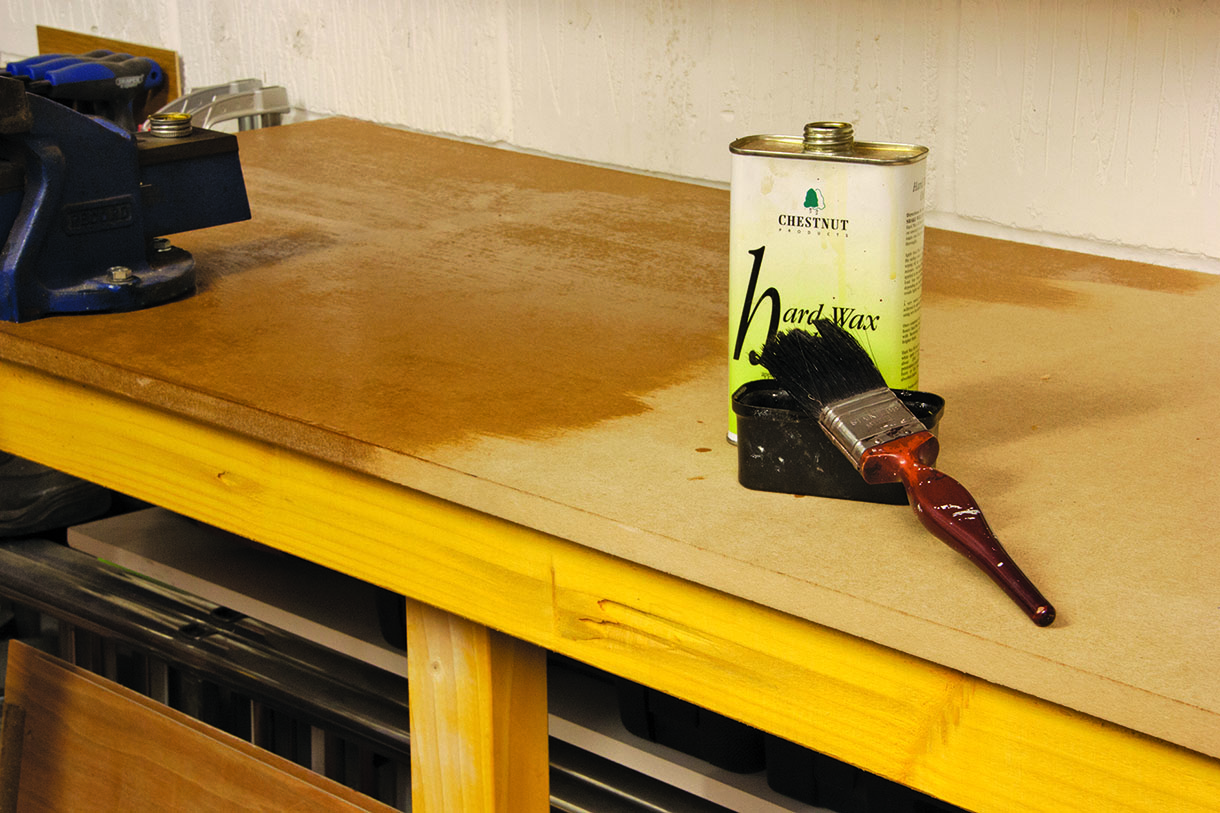
The MDF top was sealed using several coats of hard wax oil to make it impervious to dirt and fluids
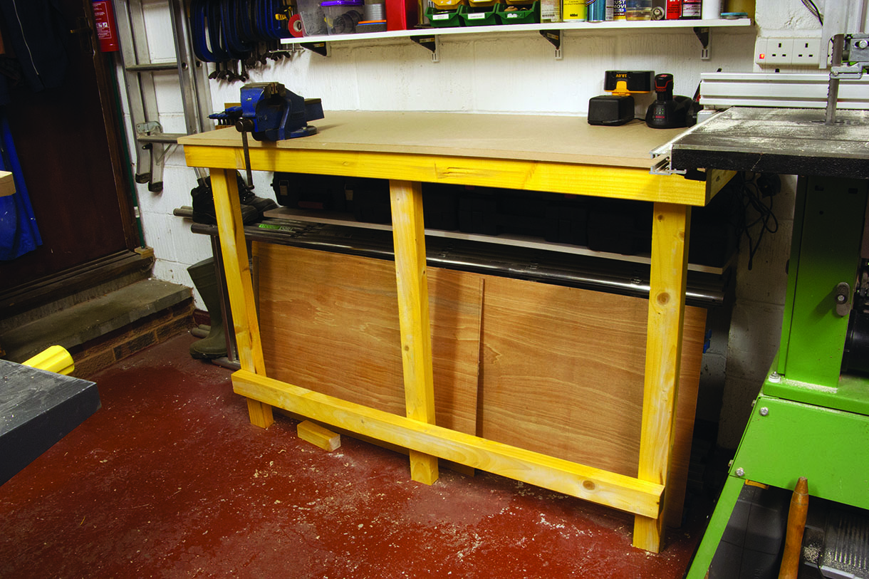
With my engineer’s vice mounted the bench was almost ready for use


