Gothic-Style Oak Screen:
Louise Biggs archly describes how she made an oak screen for a very particular client
Louise Biggs archly describes how she made an oak screen for a very particular client
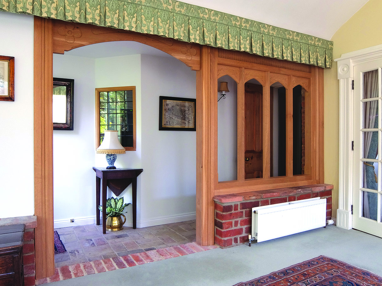
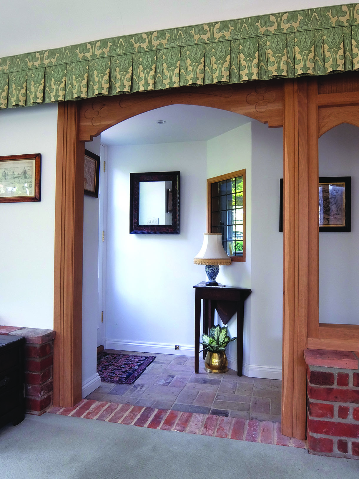
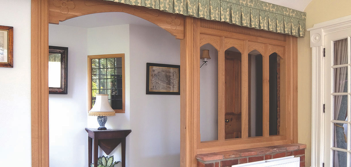
I have restored several items of antique furniture for these clients, but this time they came to me with an idea for an oak screen they wanted installed between their conservatory and corridor. As Mr Martin lives in an old cottage and is very interested in architectural and building history, he prefers the details of the work done on his house to be historically accurate and in keeping with the age of the rest of the cottage.
Armed with detailed drawings of the design and carved decoration, we sat down to discuss the complexities of building and fitting the screen. Mr Martin requested that his building specialist, Barry Boutall, fit the screen on site. As this involved using Acro stands that were supporting the two adjoining ceilings, I was only too happy to agree. The jointing of the outer frame would be crucial as this would have to be delivered in sections and put together on site in order to get over all the hurdles involved, but was built and assembled in the workshop first.
The screen would be made from North American white oak. The necessary timbers were prepared to size and the mullions and all relevant mouldings milled to the required profiles.
Tools used
• Tablesaw
• Planer/thicknesser
• Router table and routers
• Mortiser or mortise chisel
• Bandsaw
• Router cutters – straight and shaped to suit profiles
• Wooden and rubber mallets
• Chisels of various sizes
• Spokeshave – round bottom
• Try-plane and smoother plane
• Squares various sizes
• Sliding bevel
• Mitre cutter
• Tenon and dovetail saws
• Plug cutter
• Drill and drill bits
• Cabinet scraper
• Abrasives
• PPE – breathing and eye protection
Wood
• North American white oak (Quercus alba)
Site assessment
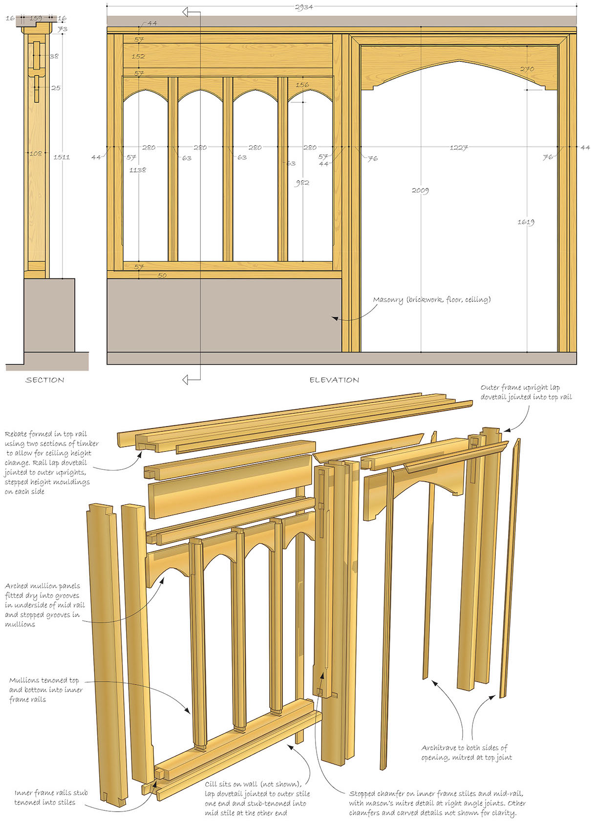
1. The outer frame would be constructed dry. The inner window and door frames would be glued. There was a 29mm step between the ceilings, so the top rail of the outer frame would have to be fitted from the conservatory side. At the inner wall (far side of the window section), the upright would have to be fitted from the conservatory side due to the step in the walls. At the outer wall (far side of the door section), the upright would be fitted from the corridor side. Some plaster had already been removed when taking out the original fixture
2. The door upright and the central upright were further complicated by the tile capping on the walls, which projected past the line of the walls. The details of the wall alignments can be seen on the drawing
The outer frame
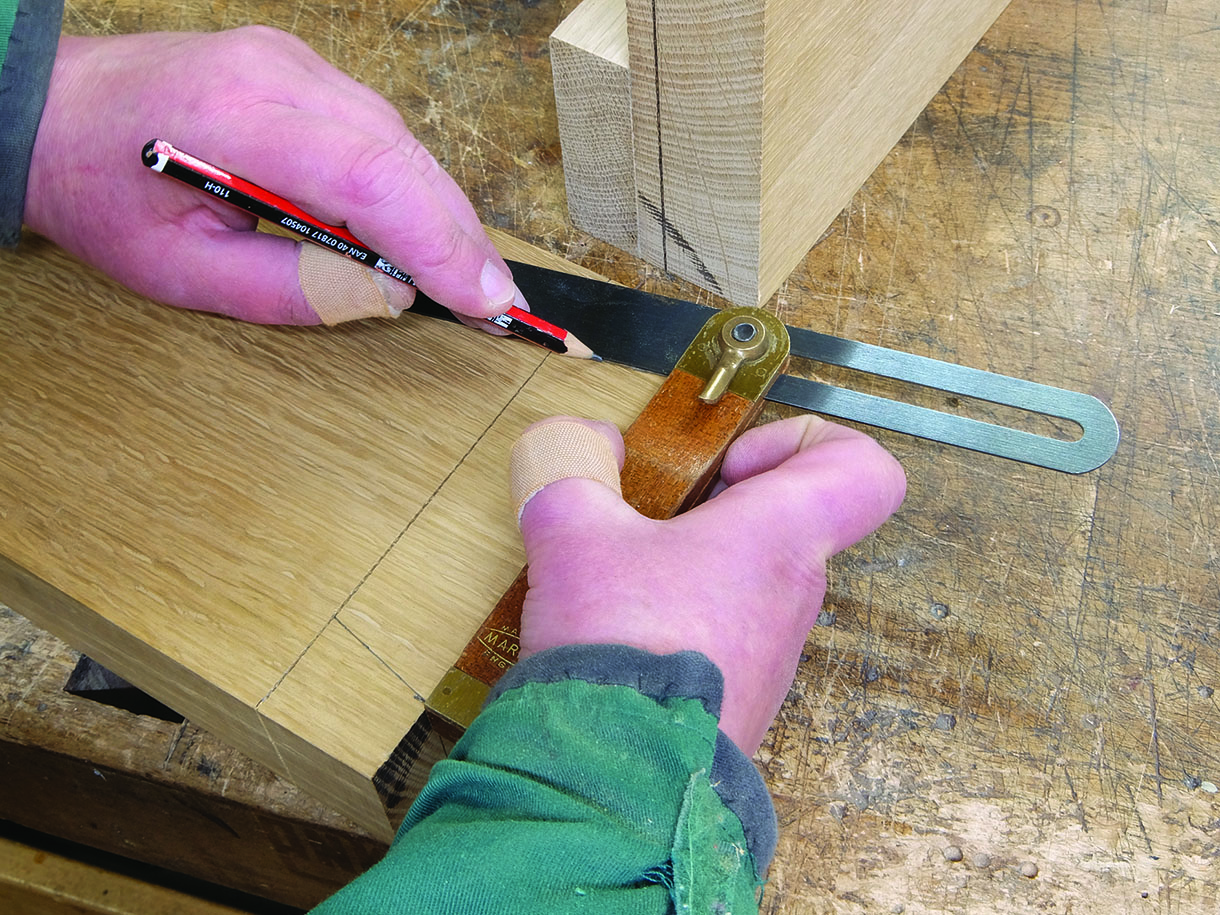
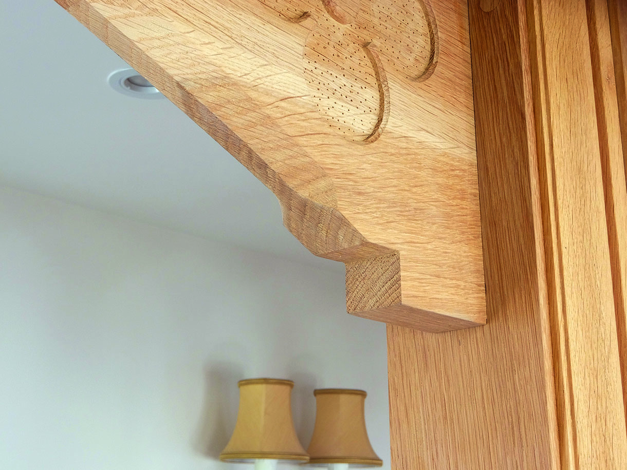
3. I started with the top rail, joining the two sections of timber together to form the rebate which would follow the step in the ceiling heights. This was glued and clamped together and left to dry before the wider joint edge was trued up using a try plane. Lapped dovetail joints were used at either end of the top rail, to allow for the rebate. Using a marking gauge, the width of the ‘lap’ was indicated on the top rail and the corresponding width was then marked on the two outer stiles. The marking gauge was reset to the thickness of the stile and the top rail gauged on either end. The ‘rake’ of the tails was then marked using a sliding bevel, set to the correct angle
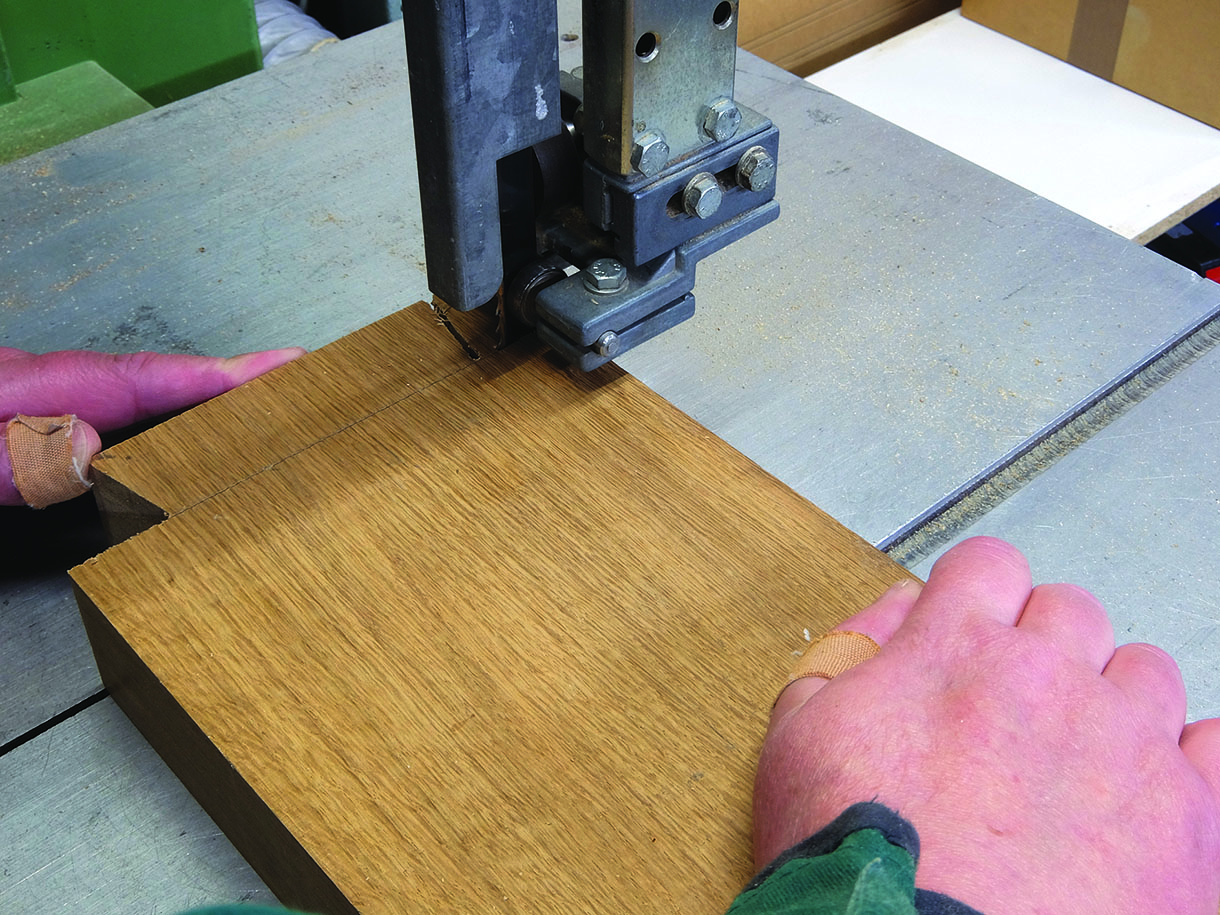
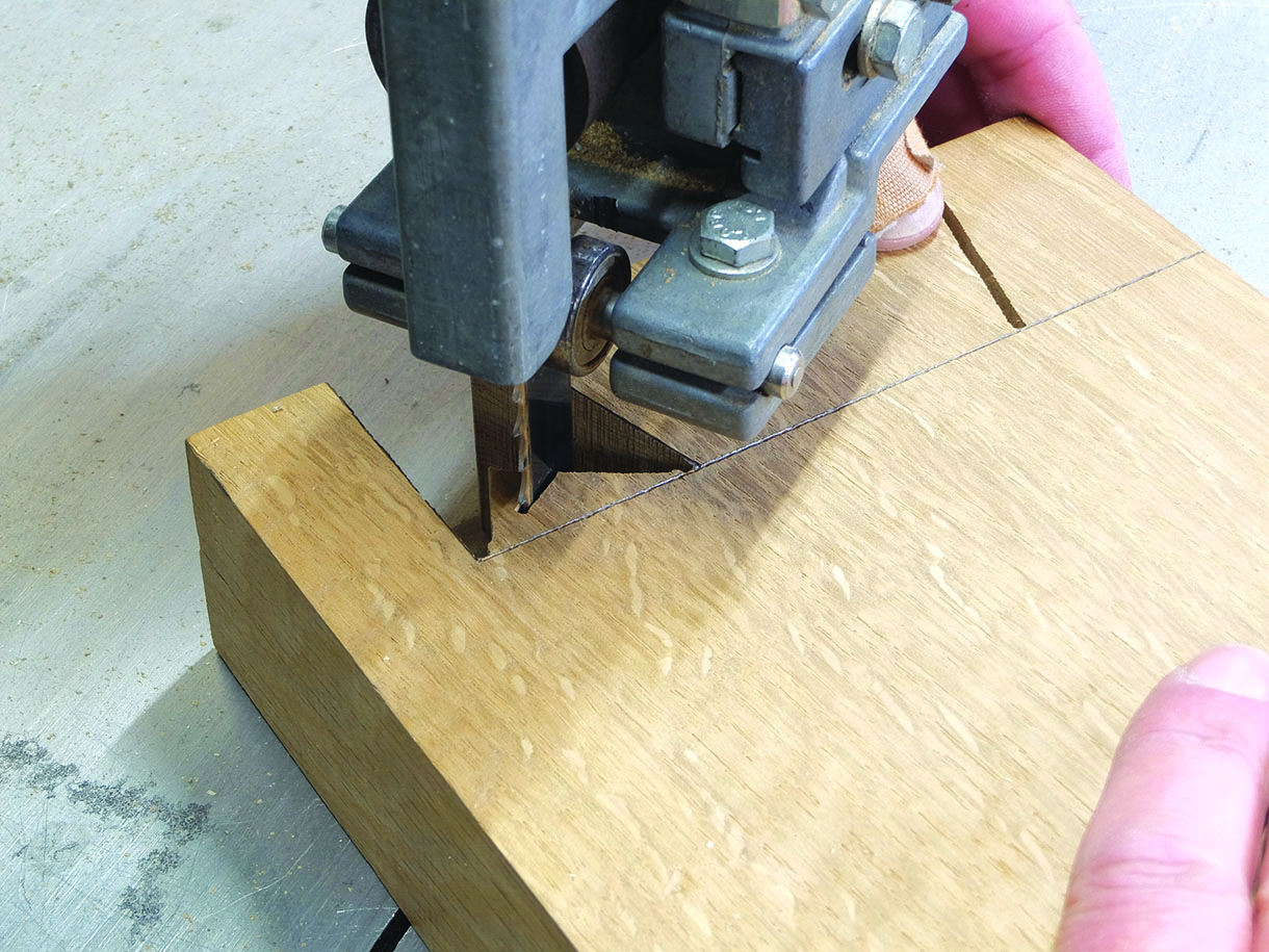
4. The tails were cut out on the bandsaw and the length of the timber was supported on a roller stand, with a friend guiding the other end. These can also be cut by hand, using a tenon saw due to the size and space required. With the tails cut out, the faces and shoulders were trimmed up with a wide chisel. A final check ensured that they were square
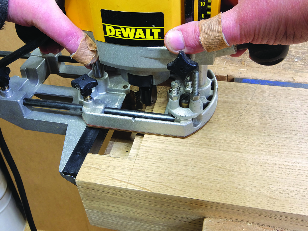
5. The stile and rail were aligned to mark the position and shape of the tail. To make life a little easier,
most of the waste was removed using a router. With the depth gauge set, small steps were routed out in width and depth until the shoulder line was reached. The remaining waste was then removed from the corners using a wide chisel. The fence of my router was such that it was supported at all times with a suitable cutter, but the traditional method using a chisel and mallet could also be used
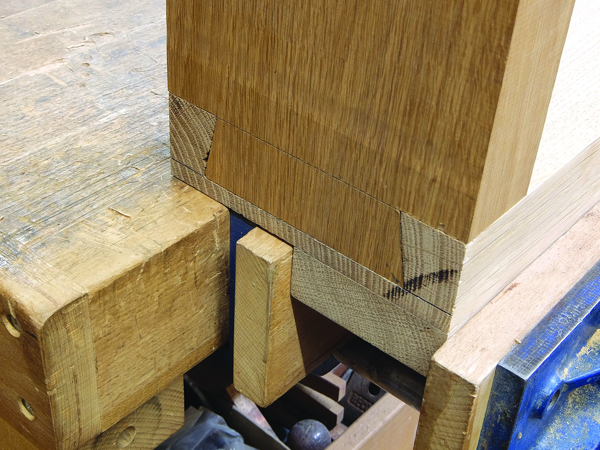
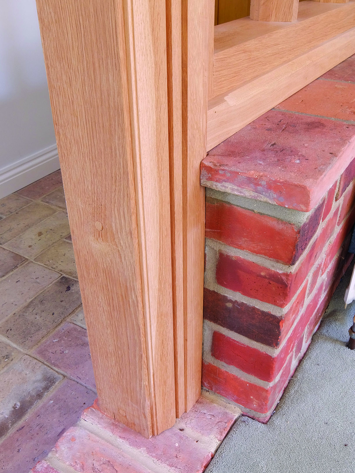
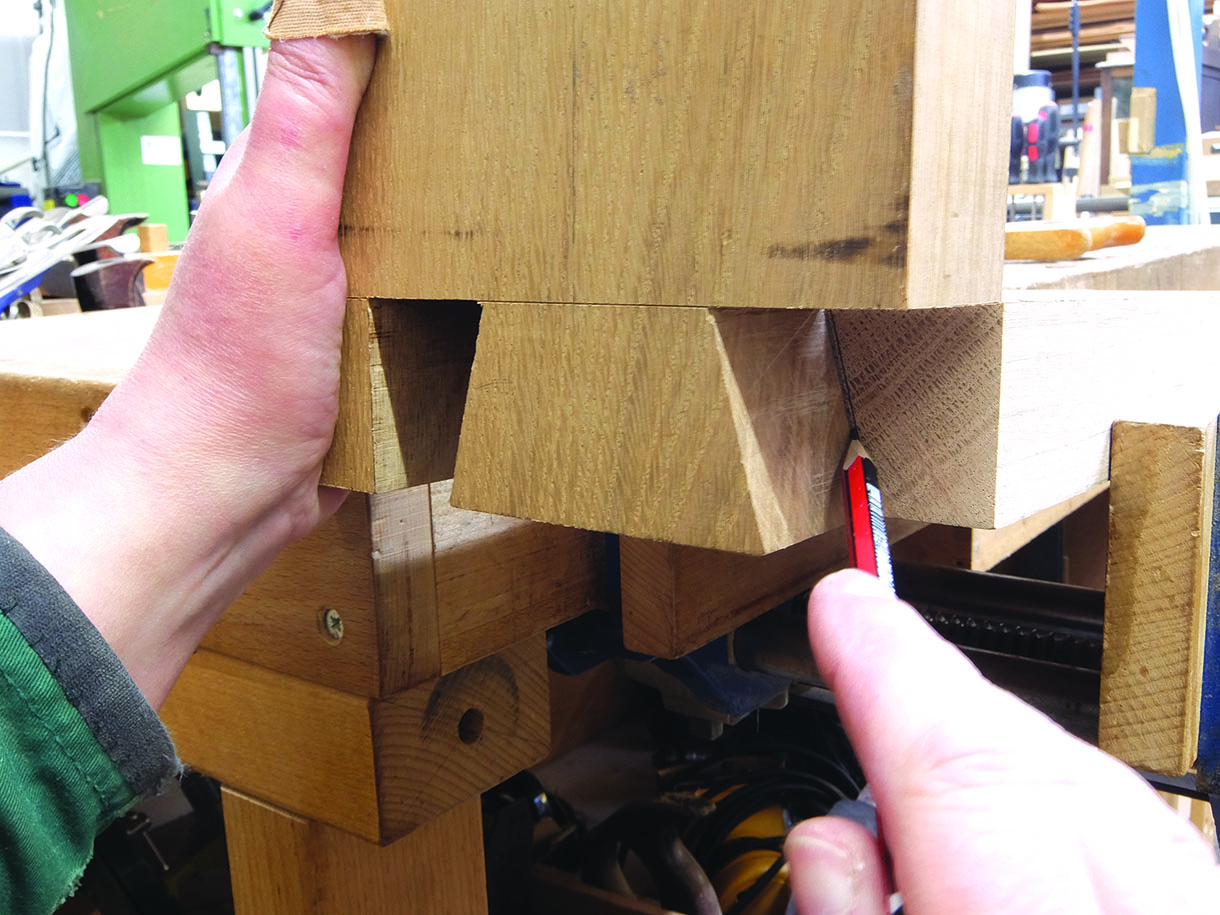
6. The fit of the lapped dovetails was tight enough to do their job, but loose enough that they could be pushed together for erecting on site. The bottom cill was to sit on the existing brickwork and would be pushed into place on site, once the top rail and outer stiles had been cleverly manipulated into place. A through dovetail was used, which had to allow for the difference in widths as the cill was 25mm narrower than the stiles. It would also have a chamfer added on the top edge, on the corridor side of the screen. With the two sections aligned, a square was used to mark the width of the cill on the stile
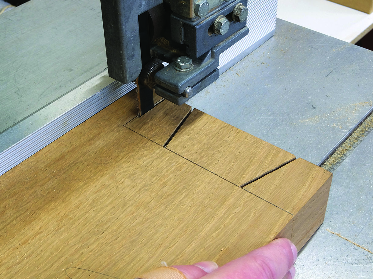
7. The same procedure as the lapped dovetail was used to mark the depths and widths of the joint and timber. With the square shoulder marked, the rake of the tail was positioned. The tail was cut on the bandsaw, with the timber supported and the fence put in place to cut the straight shoulder created by the difference in widths
8. With space and support, and by turning the section over, the waste between the tail and the shoulder was removed by making angled cuts and gradually moving down to the shoulder line. The remaining shoulder lines and joint faces were trimmed as before
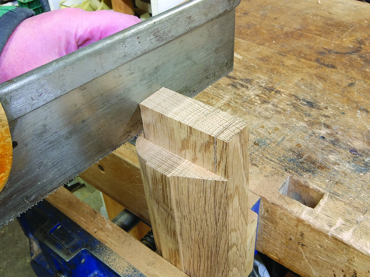
9. Supporting the stile, the sections were aligned and the joint marked on the cill section. Using a tenon saw and cutting from each side at an angle, before finishing with a straight cut, the pin socket was cut on the waste side of the lines. The remaining waste was nibbled out as before on the bandsaw and the remaining corners cleaned out using a chisel and mallet
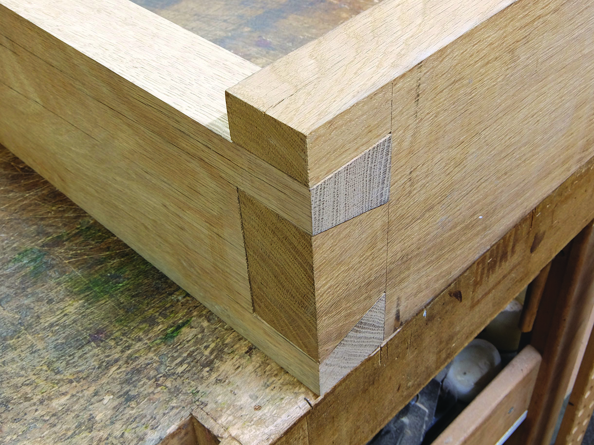
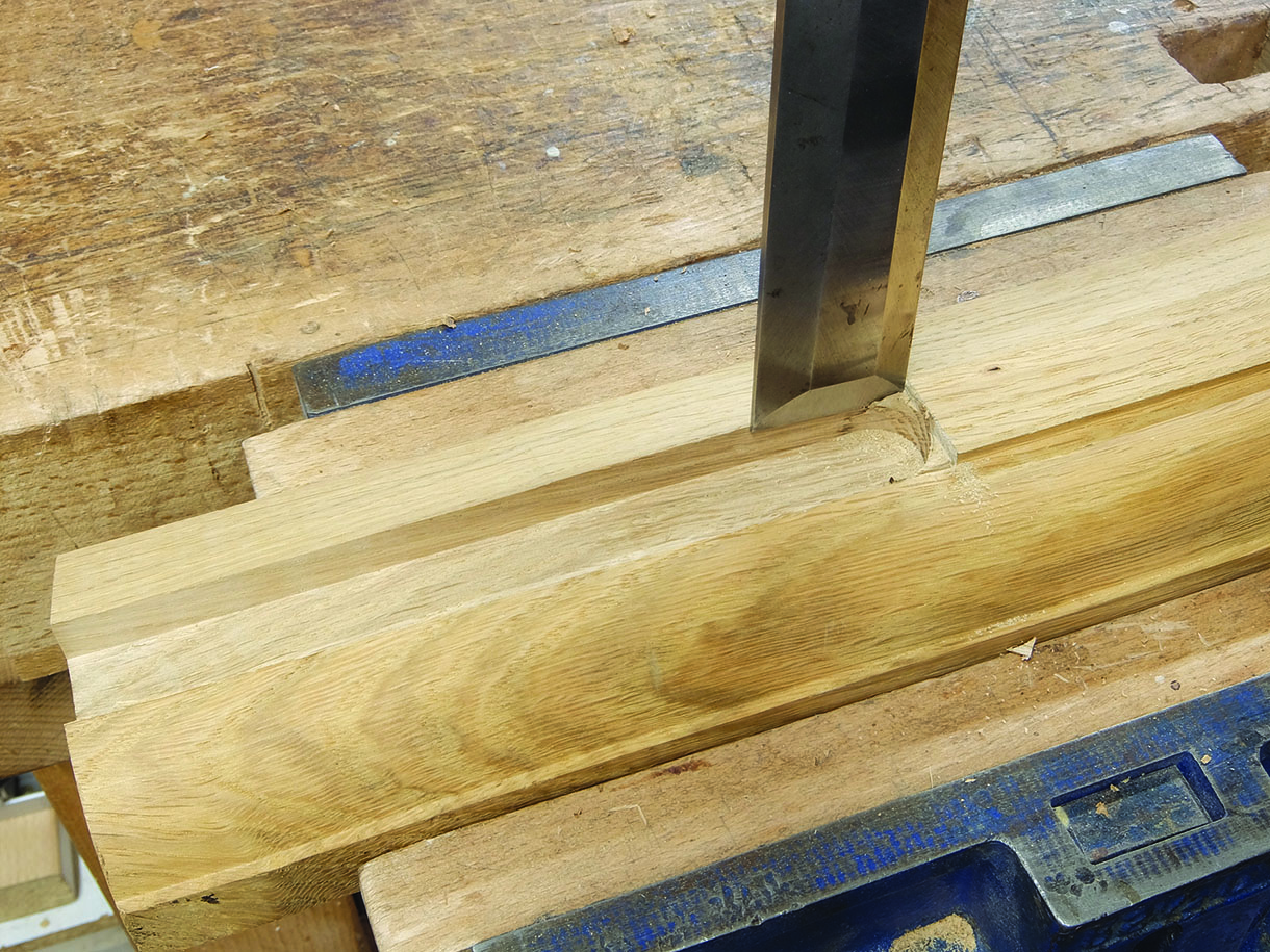
10. With the shoulders and joint faces trimmed, the joint was fitted together. Traditional stub mortise and tenons were used to fit the central stile to the top rail and cill, and with more manipulation, could be eased into place on site
Window and door frames
11. With the outer frame assembled dry, the cill was supported and the outer stiles screwed to battens, which were cramped to anything available to keep the frame upright and in line, so that the inner frames could be fitted. The window frame was mortise and tenoned together, with the tenons being horizontal due to the width and thickness of the sections. These were cut using a mortiser and a router set up on a table. As there was to be a chamfer running along the bottom edges of the mid rail and down the stiles, using an off-cut with the chamfer cut, the position of the shaped mullion could be worked out
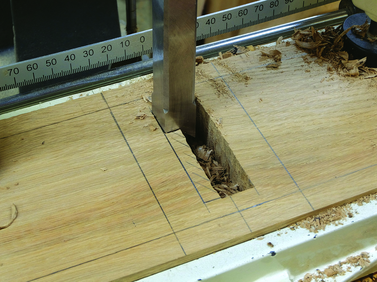
12. With the correct position found, the mortises were prepared on the mortiser using the lateral movement of the table to cut from front to back
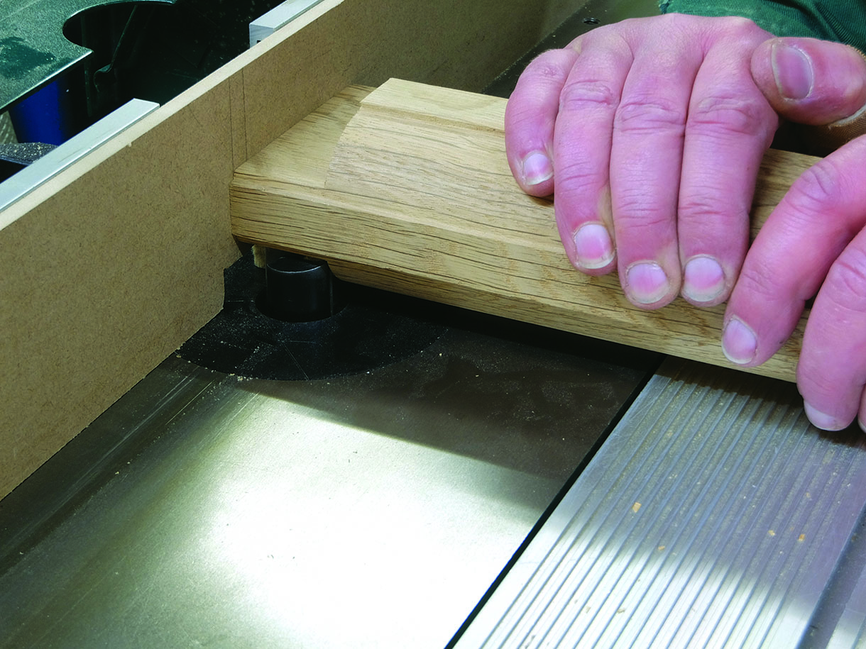
13. The two main cheeks and shoulders for the tenons were cut on the router table. Tenons at the top of the mullions were kept shorter than those at the bottom, allowing for a groove for the top panel
14. The remaining shoulders were cut by hand then the frame was assembled dry and fitted within the outer frame. The chamfers were cut on the router table, marking the fence with the cutter position and the stiles where chamfers were to be stopped, to align the marks
15. When glued, the stopped chamfer at the top of the stiles was chiselled out to join the top chamfer. The door frame, jointed as the window frame, was dry assembled and fitted in the same way. Both frames were drilled for oak plugs which would cover the screws, fixing the inner frames to the outer frame
Fitting the panels
16. All the panels were fitted dry within a groove, to allow them to move without splitting. The top rail and top side of the mid rail were grooved on the router table, running straight through. The stiles and mullions and underside of the mid rail, however, would need stopped grooves to allow for the arched panels, to avoid interfering with the mid rail joint. The mullions were well supported and firmly held on the flat edge as the groove was the same width. With the shoulder line marked, this could be aligned to the fence mark. Finally, the shoulder line could be cut square using a chisel and mallet
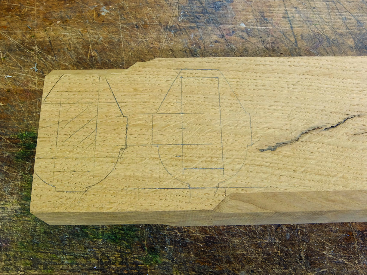
Shaping the panels
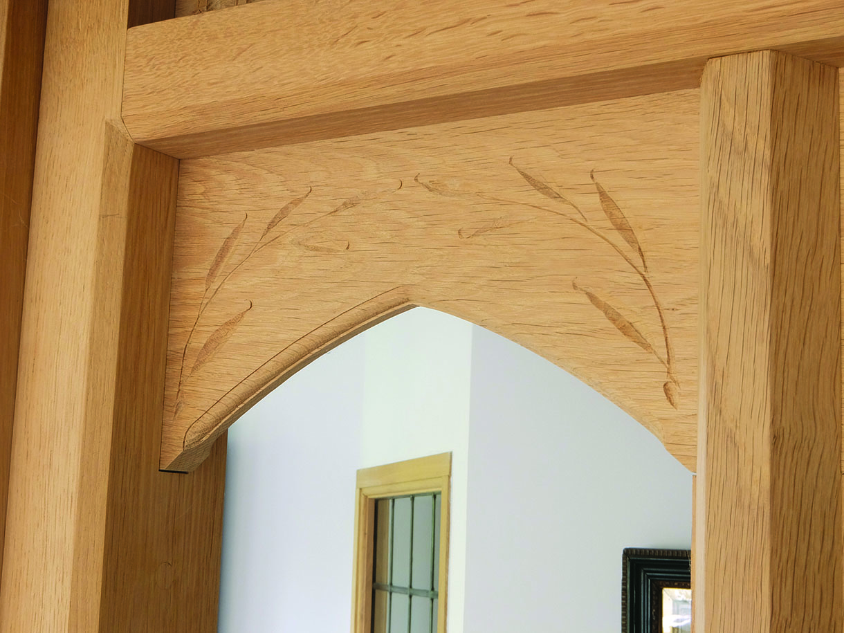
17. The arch on the mullion panels was then cut on the bandsaw and cleaned up using a round bottom spokeshave and a chisel. A stopped ovolo moulding was routed on both sides using a cutter with a bearing wheel on the router table
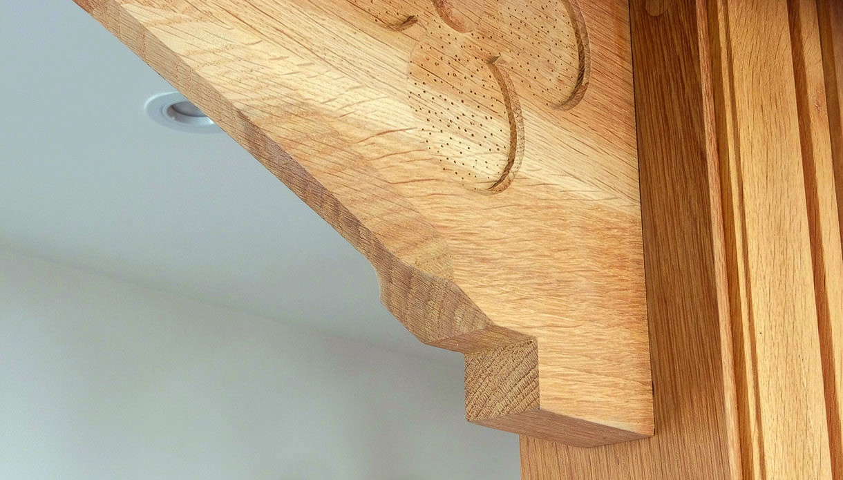
18. The door panel for the steps was cut by hand and trimmed to square before the arch was cut and shaped in the same way as the mullion panels. A stopped chamfer was then cut, using a bearing cutter
Mouldings and carved detail
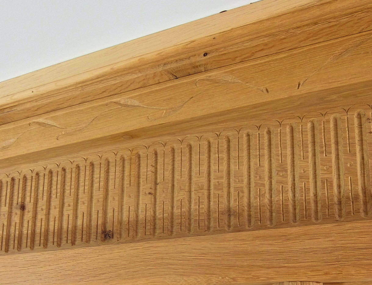
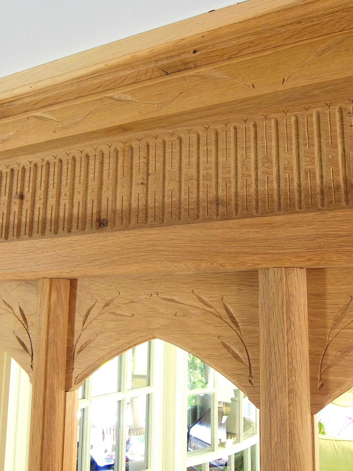
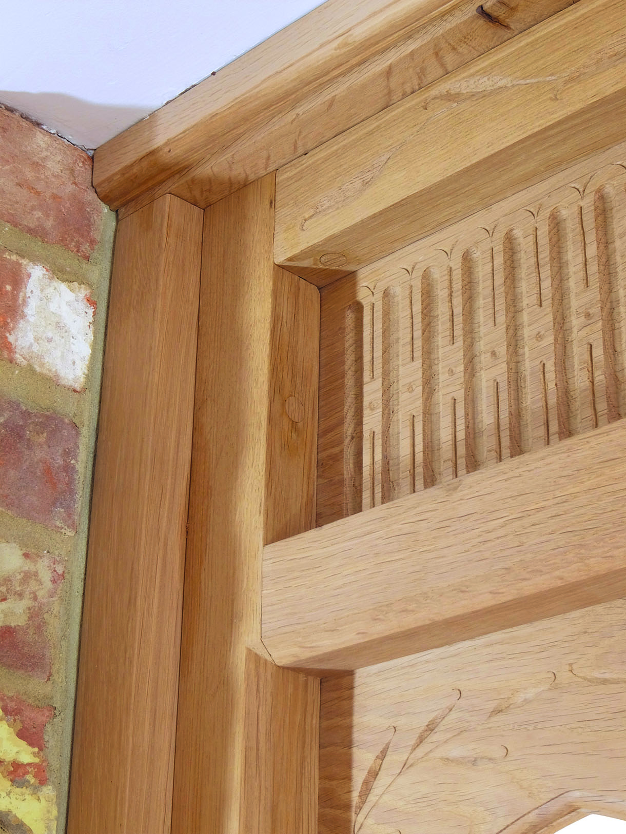
19. The panels and the top rail of the window frame were sent away to the carver Shane Raven, so that the various details and patterns could be drawn out and carved. The architrave mouldings were mitred and temporarily pinned around the door frame, while being left slightly long for fitting on site, along with the remaining mouldings
Final steps
19. The panels and the top rail of the window frame were sent away to the carver Shane Raven, so that the various details and patterns could be drawn out and carved. The architrave mouldings were mitred and temporarily pinned around the door frame, while being left slightly long for fitting on site, along with the remaining mouldings


