Wine Table:
Stephen Hogbin tells us how he made this colourful wine table
Stephen Hogbin tells us how he made this colourful wine table
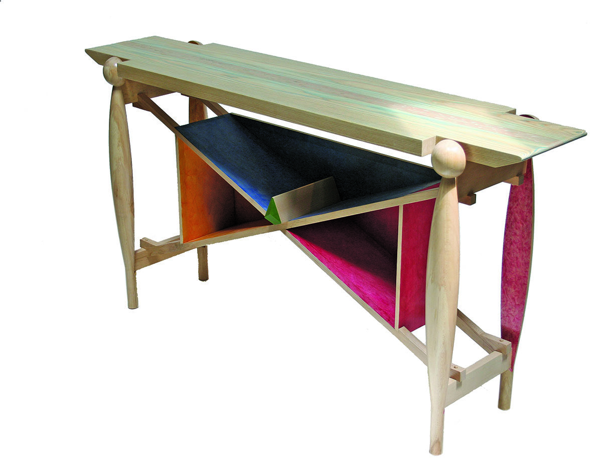
My clients needed a table to go between their dining area and the living room. It would function for both areas as a serving table and hold a selection of wine bottles. These clients have collected my work over the years and understand the development of my ideas, forms and techniques. They had made a concept sketch suggesting how the wine bottles may be stored. This proved an excellent structural solution for the table and was easy to adopt. They also suggested turned elements, carving or milling marks and colour in the table. Their living room already has two of my artworks on the wall as well as pieces of my furniture.
It is a colourful room with all the artwork referencing nature.
The table design
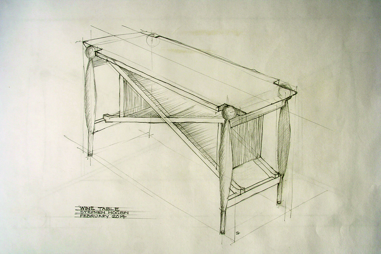
1. The table’s height and length were established in relationship to the clients’ sectional couch. The depth of the table top was determined by the length of a wine bottle. Even with these well-established criteria, I made several drawings to look at the table’s proportions. While it had to function, the clients also have a keen eye for aesthetics. The sketch and measured drawing were presented to the clients for discussion and approval
2. I wanted to incorporate turnings as their family heirloom dining table has turned legs, which are traditional and heavy. For the wine table, I really wanted to turn lighter legs that would reflect the roundness without slavishly copying the legs of the older table. The idea for the wine table included two turnings, both of which would be then split to make the four table legs. The size of each split element is identical, whether it’s cut in half or quarters. The combination of curved and straight lines brings variety to the form. Structurally, this gives some advantages and the construction is simplified with flat planes, to which rails may be attached
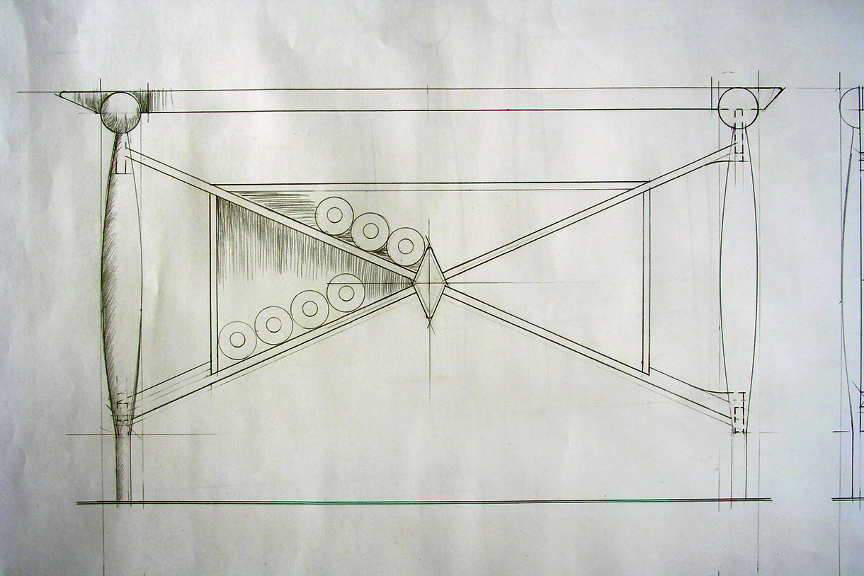
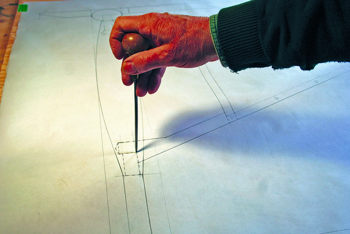
3. A full-size drawing was made on a sheet of plywood. The design of the table required accuracy of all the parts, especially the X frame. From the drawing I could see precisely what the proportions would be and could assess the details of the joinery. Marking out the shape of the X frame became easy
Wood
• Ash (Fraxinus americana)
• Maple (Acer rubrum)
Turning the table legs
Two or four legs could be made from one turning by preparing the stock as either two boards or four boards. It is preferable to hold the square parts together at both ends with stainless-steel band clamps.
Split turnings are best pre-finished on the inside of the turning. I prepared the boards and finished
the inside before fixing them together. You can see in the box below that I have demonstrated three different ways to prepare the turning blank for going on the lathe: the quick way, the half way and the best way. The best way keeps the square cross section on the ends, which will be useful at a later stage.
The quick way
Using this method, the corners of the parts are removed on the tablesaw.
The loss of the square could prove a disadvantage when drilling, mortising or carrying out additional operations. Also the band clamp, which is strong, comes in various sizes and can be reused, does not fit snugly and may even bend the clamp. That may not be an issue but it does not feel so well engineered.
 The half way
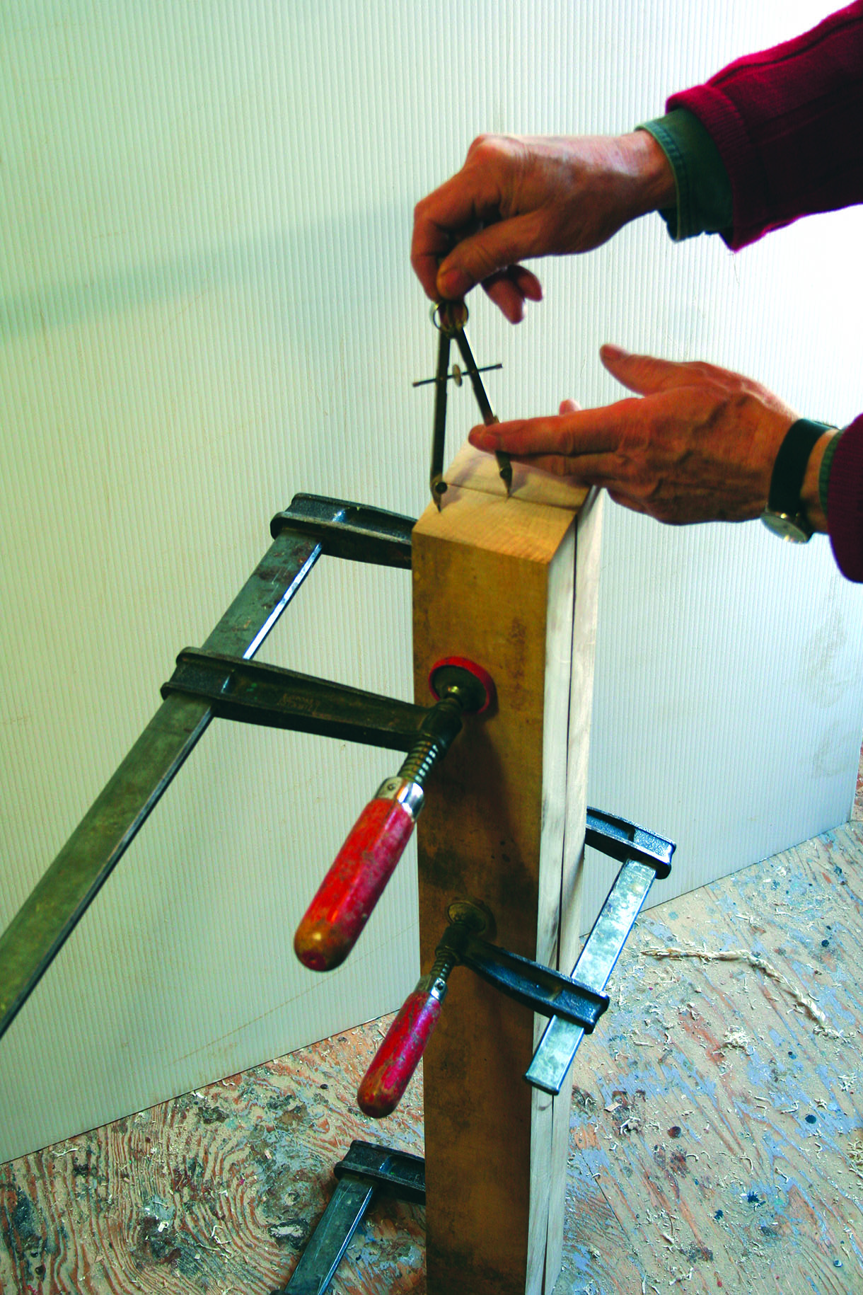
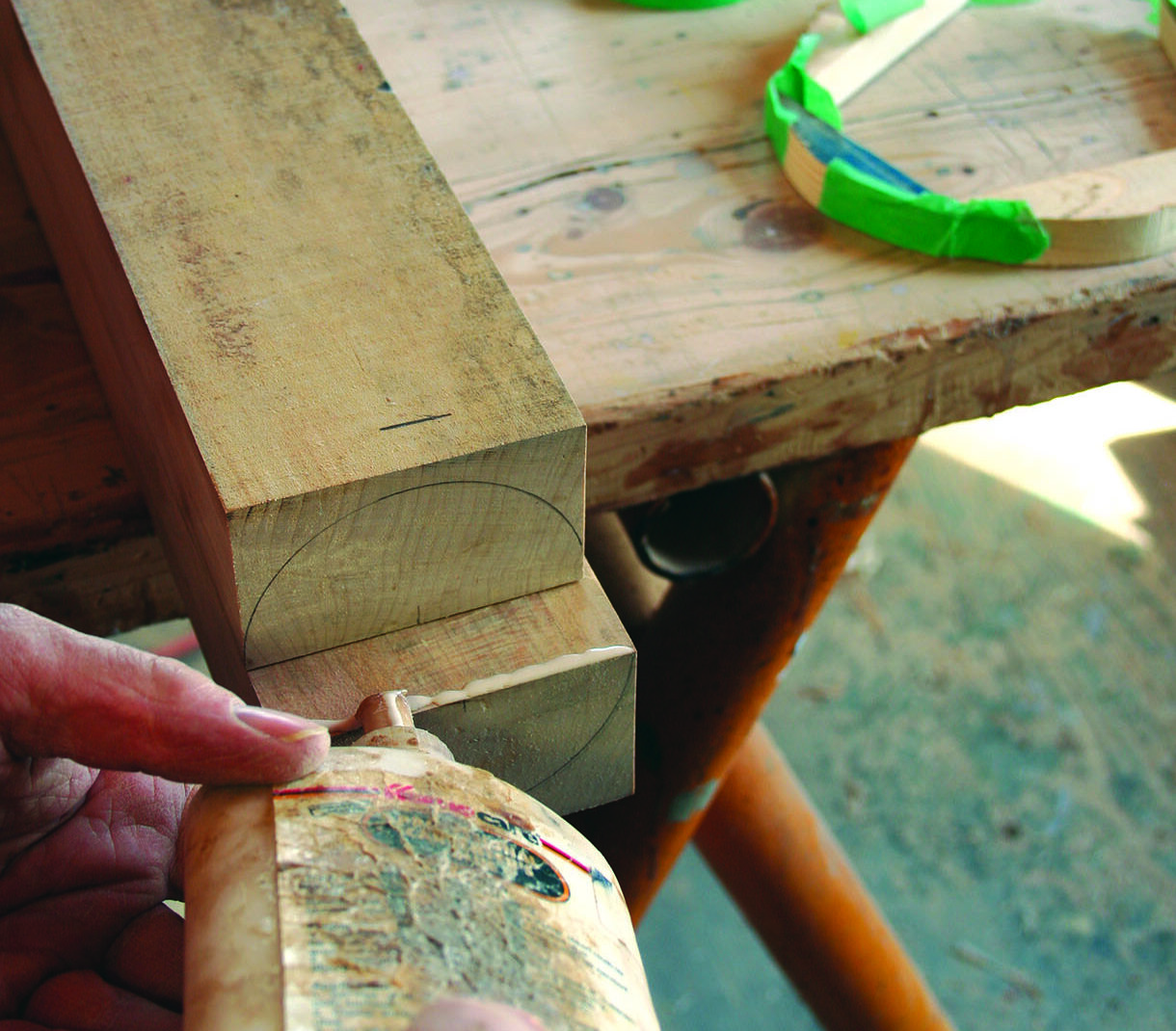
The boards are held together in this method with clamps. The ends are then marked with a circle using a compass. Square around the parts the width of the band clamp. Now cut with a hand saw to the square edge, as deep as the diameter. Chisel off material to the diameter and the square edge. Attach the band clamp. This becomes a well-fitting clamp while retaining the square cross section.
 The best way
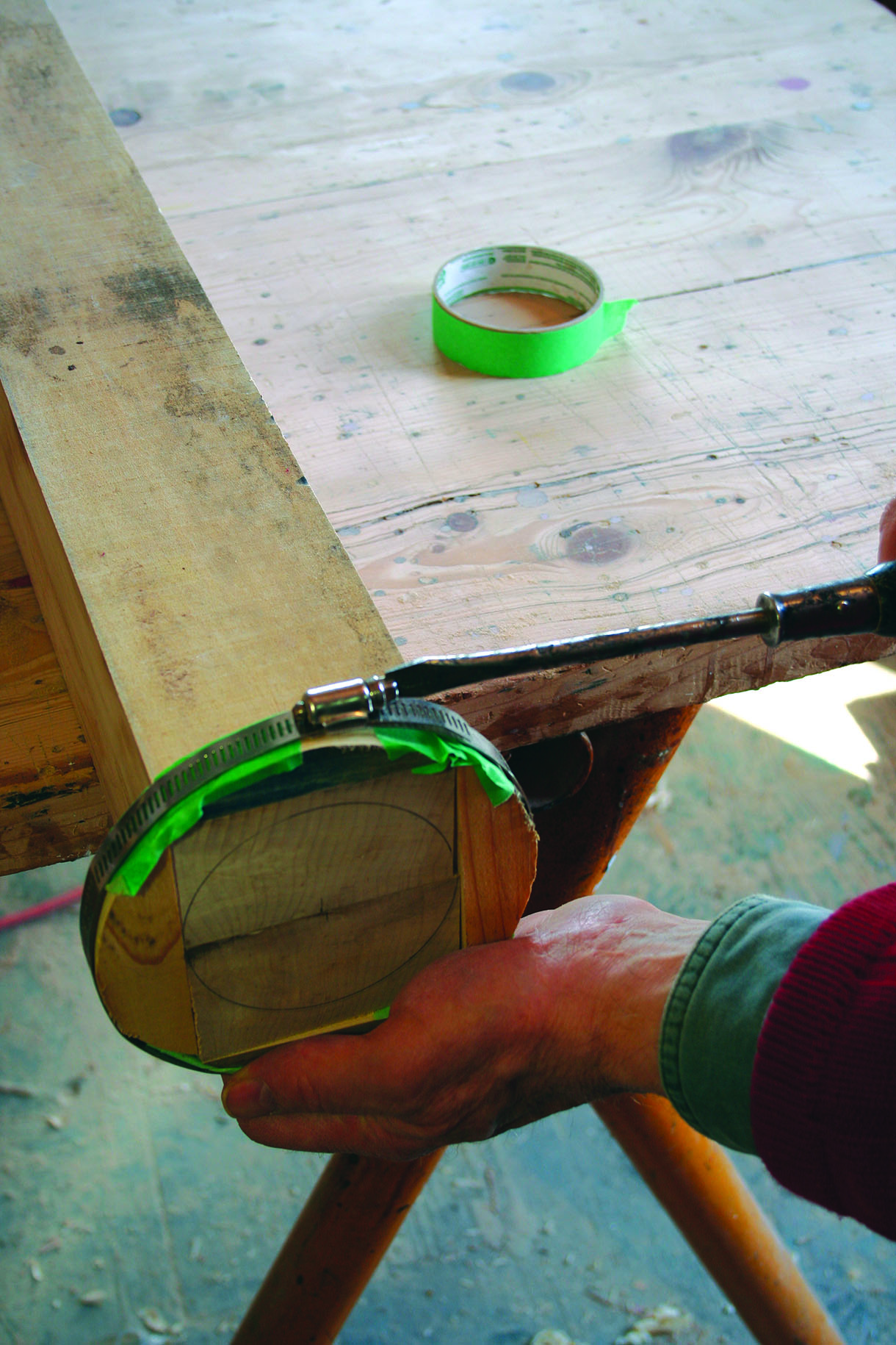
The best way is also unfortunately the slow way. The parts are kept square to the maximum length. Crescent shapes are cut on the bandsaw, then green taped to the square cross section. The band clamp fits smoothly and it’s all easy to remove. The setup is fiddly, but well worth it in the long run. The crescent shapes, like the band clamp, may then be used again.
 Next steps
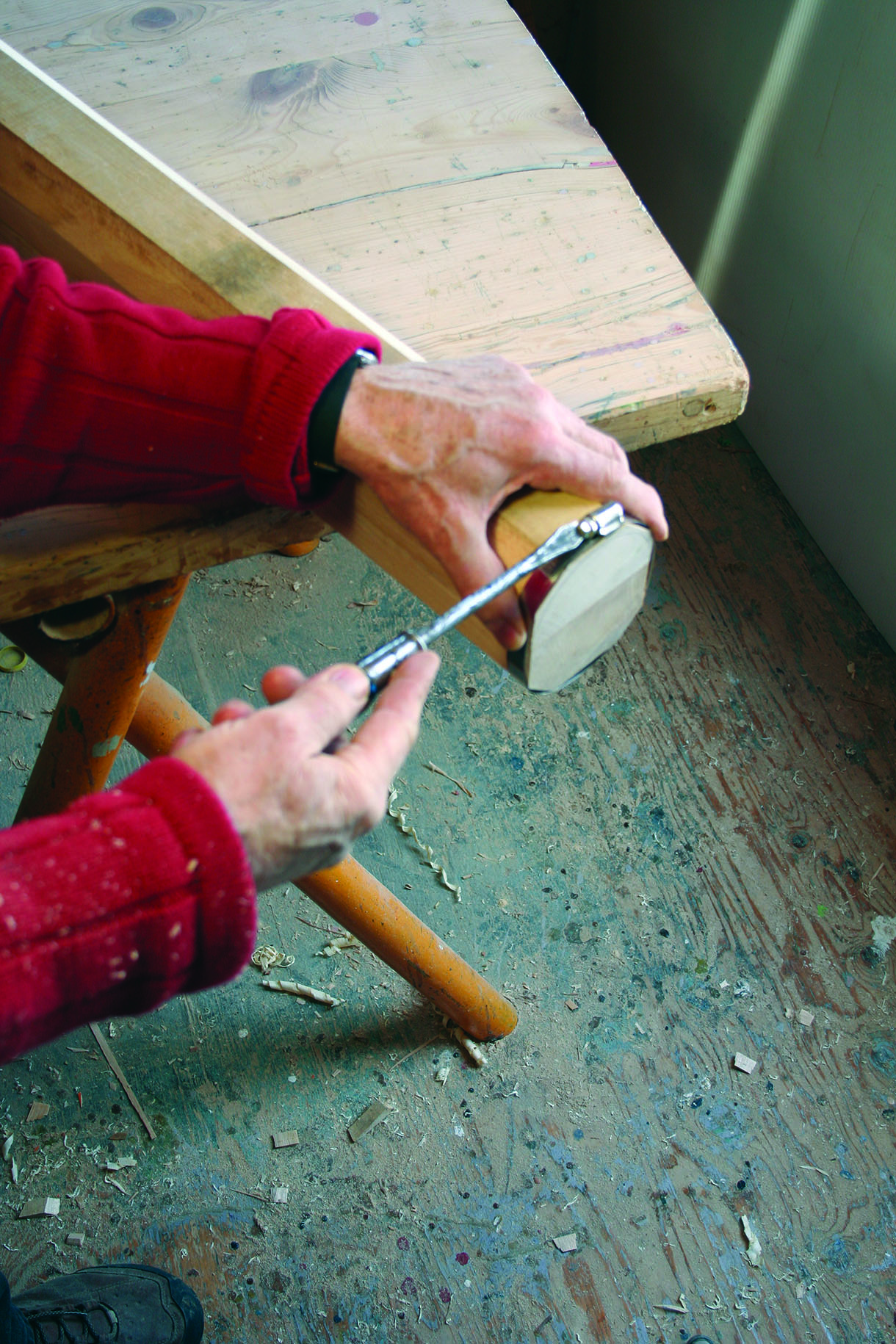
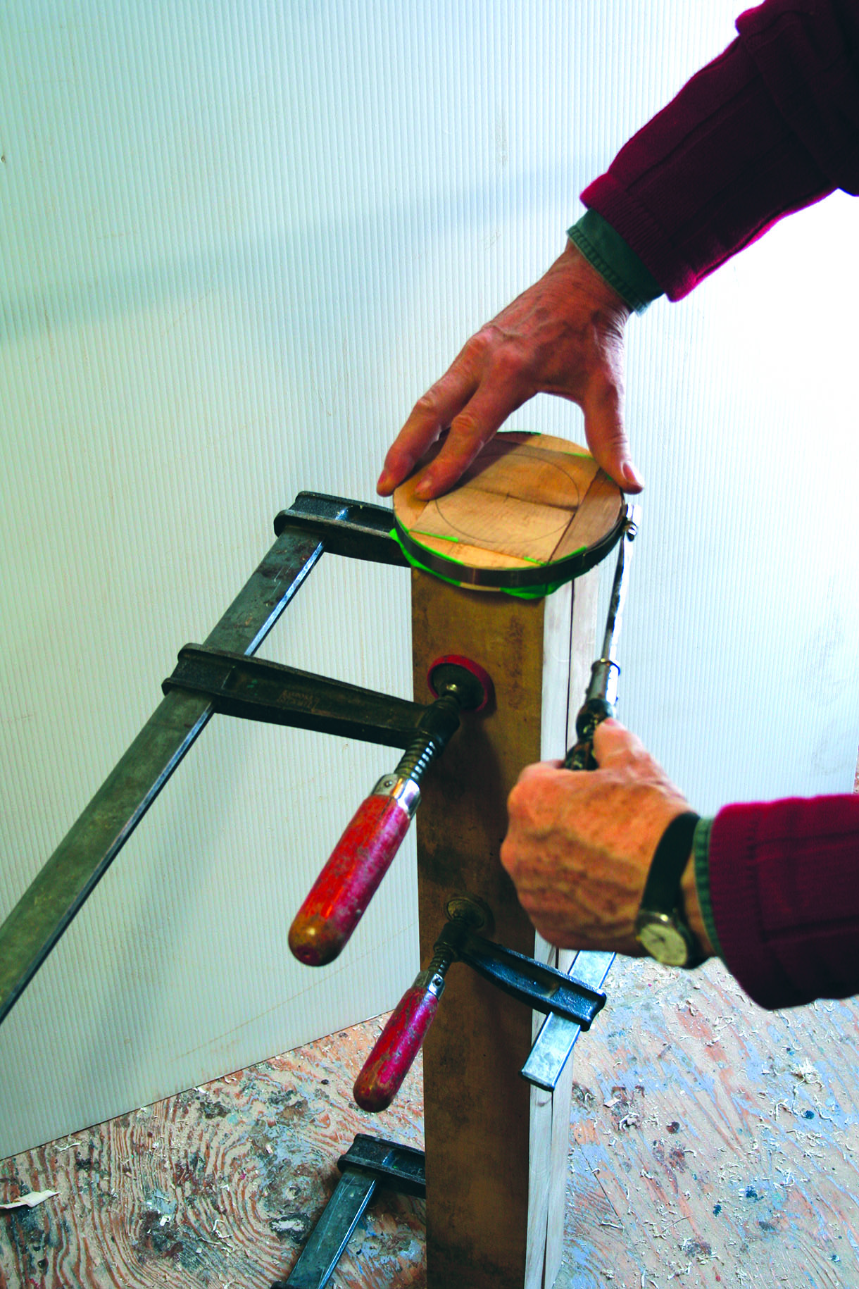
4. It is essential to add a tiny bead of glue on the ends before the final band clamping. I used a 3mm PVA bead to secure the relationship of the parts. When the turning chisel catches, the parts want to slide in relationship from one to the other. To take it apart, a sharp chisel and a gentle tap on the end of the turning will separate the parts. Cleanup is easy as the very end is probably waste material
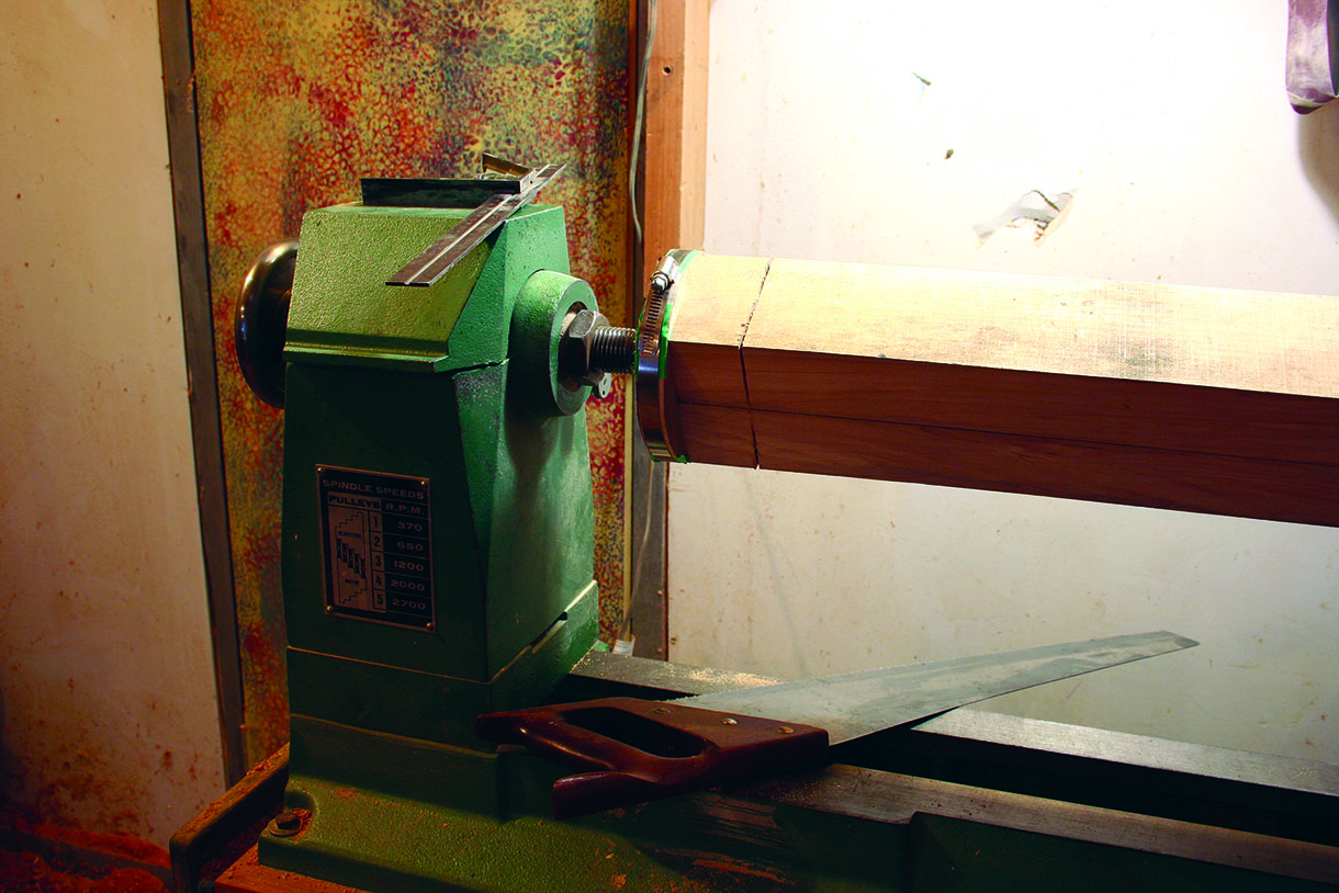
5. The blank was placed into the lathe and the length of the leg was marked and scribed around with a square. Using a hand saw, I cut down approximately to the radius of what would be turned. This prevents the square block on the end from splintering. A production turner would be able to machine this, but I am suggesting a simple way to avoid mishaps caused by a chisel catching on the piece
Making the rails
6. All the rails for the table were cut to dimension, stacked or clamped and left for a week to settle down to an equal moisture content with the studio workshop. The surfaces were then belt and orbital sanded to 180 grit as I needed the parts. When it was assembled, the final sanding went through 220 and 320 grit papers
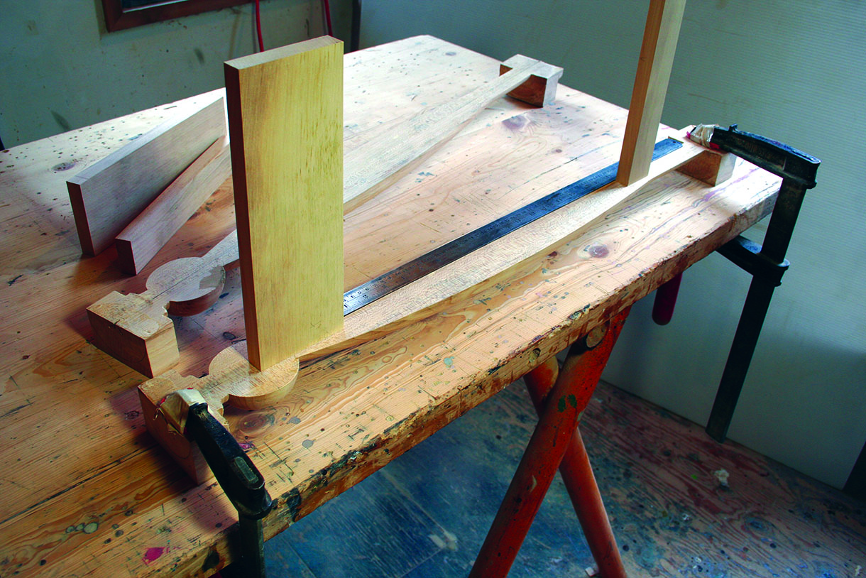
7. Marking out the X rails was very easy with a full-scale drawing. I took one of the oversized blanks for the X frame and laid it under the drawing. The finished face had to be up. I thought about the grain pattern when positioning the wood as there were structural and decorative considerations. The lines in the grain needed to run parallel with the edge of the rail to be cut out. This not only looks stronger, but is also structurally stronger as it avoids the short grain. I used an awl to mark where the lines intersected, then removed the board from under the drawing
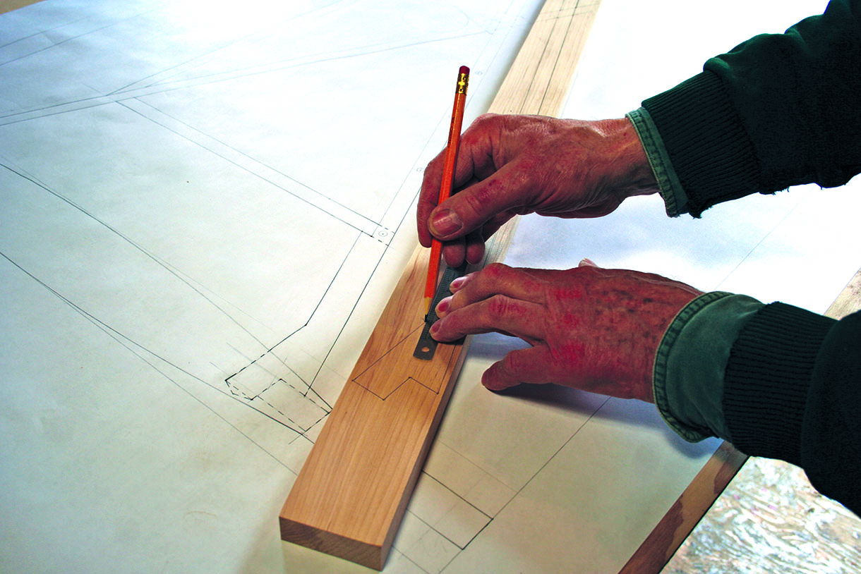
8. A straightedge was used to connect the awl punch marks
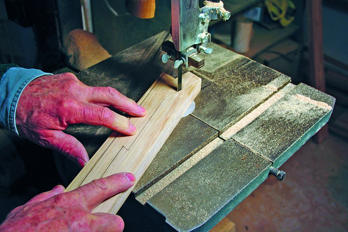
9. I used a bandsaw to cut out the shape. I prefer to not get too smart and end up with no line, so I cut just next to the line, knowing that taking care with this cut will save a lot of time when cleaning up. The pencil line was needed as the bandsaw marks were removed. I used a smoothing plane for the straight runs and a couple of files for the rest. On this occasion, I used a bastard file and mill files. The mill file leaves a fine finish that will need minimal abrasives. A square was used to check that all surfaces were true and at 90°. The cutout rail was used as the template for the next X rail. I paid close attention to grain pattern when laying it on the next oversized blank. There is a left and a right for the front and the back. I kept the very best grain pattern for the front of the table. These rails are long and slender. They didn’t feel very strong at this point. After laying the template rail onto the next blank, it was clamped down. I placed a straightedge next to it to make sure it had not deflected. Even a pencil could push the template one way or another if it rides into the grain. I drew lightly around the template before taking it apart to go over everything with a steel straightedge. The rest could now be marked out. I used the small bandsaw with a new blade, and checked everything for square. I kept all the offcuts as they would be used to make lipping on other parts of the plywood wine holder. The edge that had the bandsaw marks was planed with a smoothing plane and the last parts with rasps, bastard files, mill files and abrasives
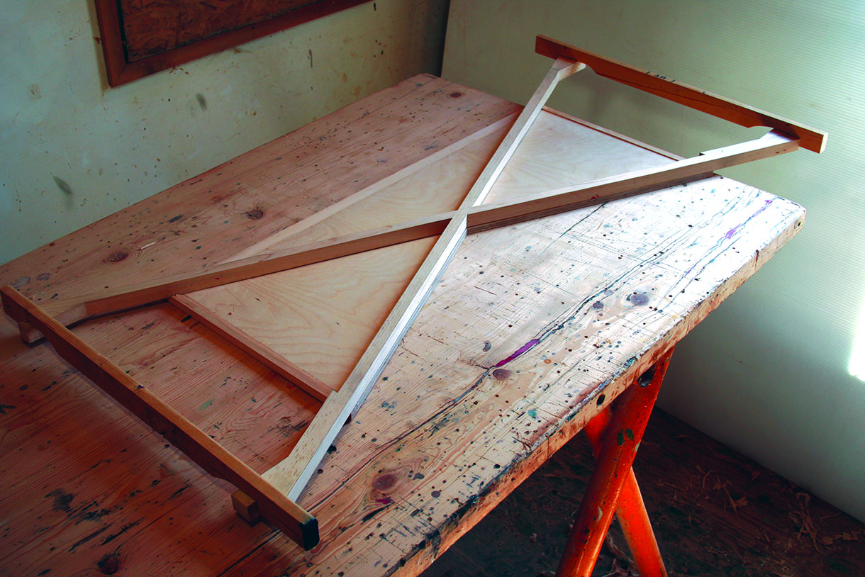
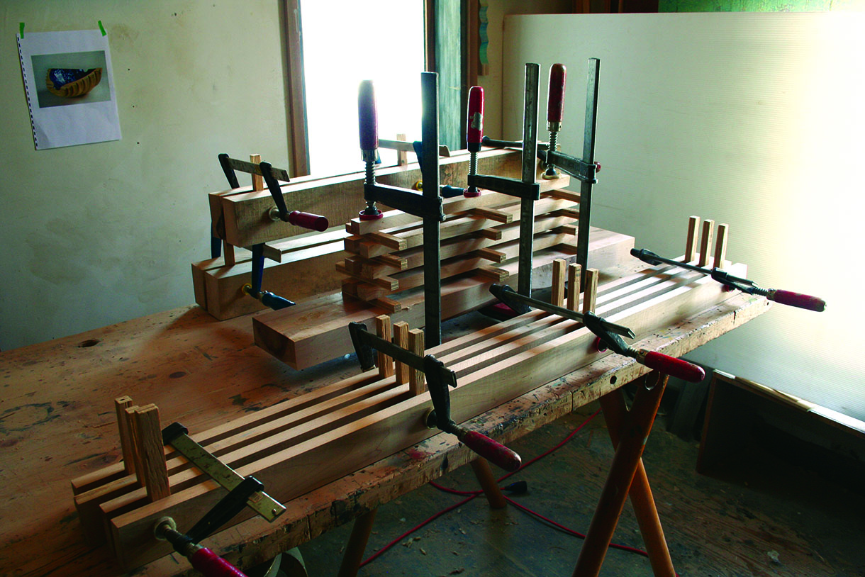
10. With the two X frames prepared, I made a cross halving joint. The rails were laid on the drawing to get the correct angles. There were two spacing strips on the ends holding them in the exact relationship to fit the table rails. The dimension was taken from the full-size drawing. Spacers were kept on all the time I was working. The plywood was cut to fit the rails. Although edges here are lipped, these could have been left to expose the plywood structure for a contemporary look
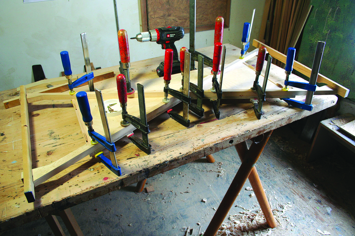
11. The back X frame was glued and screwed to the plywood back. The next morning as I took off the clamps I had one of those enlightened epiphanies on how to make this method much quicker
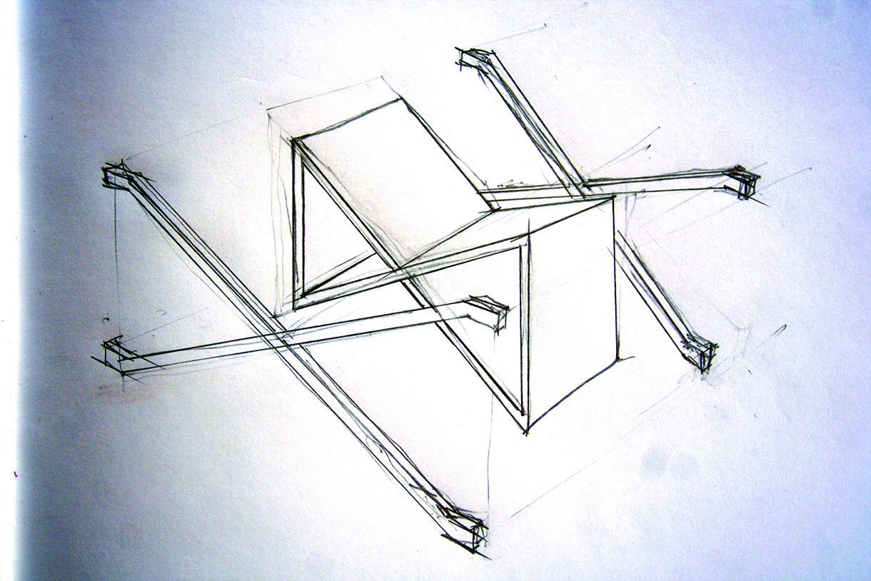
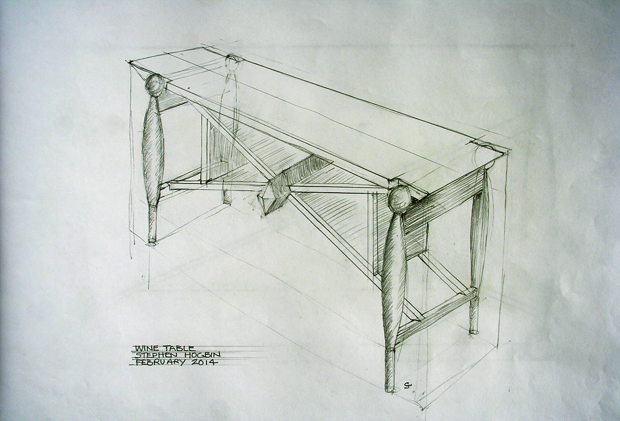
12. Instead of integrating the box into the frame, I discovered that it could be expressed as a linear structure holding a box – which can be seen in the above illustration. Conceptually and visually, the form of the table becomes clearer. With a traditional first solution, the second is more contemporary. There is no wrong or right method, rather different ways to make and express the possible ideas for the wine table. The concept drawing shows another way of creating the project. Make the box and the table frame independently. Pre-finish everything and then fix the two together using screws and plugs as the most direct solution or biscuit joint for a hidden connection
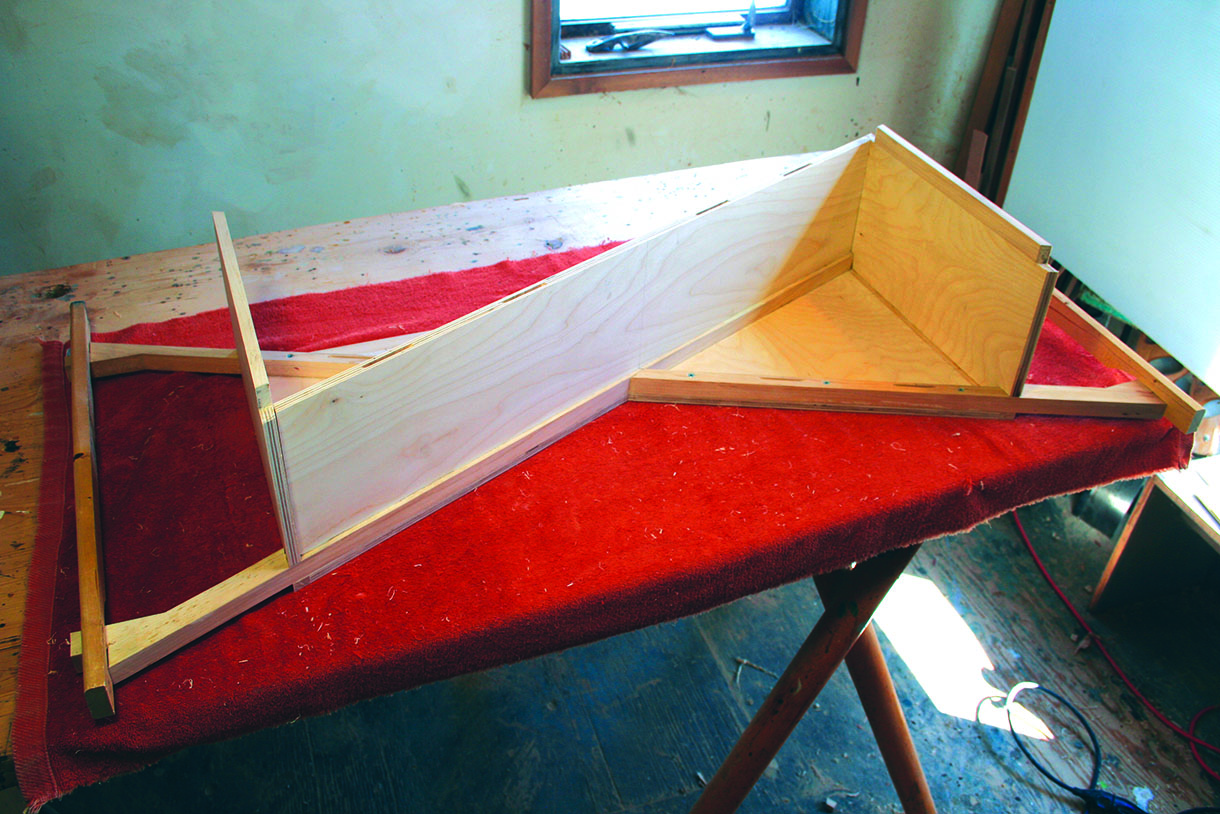
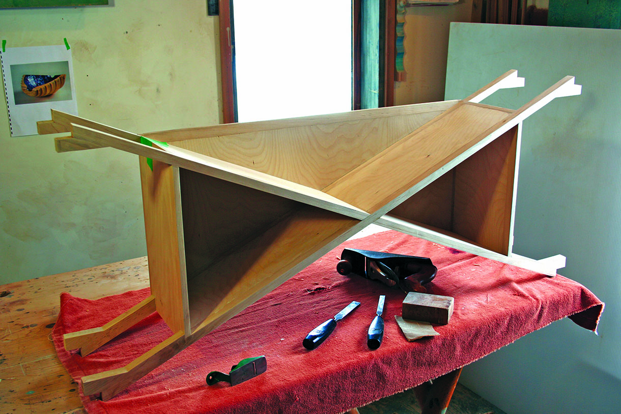
13. Rather than remake many parts, I proceeded with the first idea and started to build on the glued-together back panel and X frame. The end panels were fitted, followed by the first diagonal. The front X frame was also fitted on top. The parts were joined together with biscuits, which was a useful method for helping to locate the plywood and frame. Next, I glued the end panels and the first diagonal, but not the front X frame at this stage. The front frame was fitted dry while the plywood box was gluing. Then I glue-fixed the front X frame. A good principle is to only glue two pieces of wood at a time. That seems the best way to maintain total control. Inevitably, though, the design does call for more than two pieces on occasion
14. All the beads of glue were then cleaned off. I prefer to do this part when everything is really hard
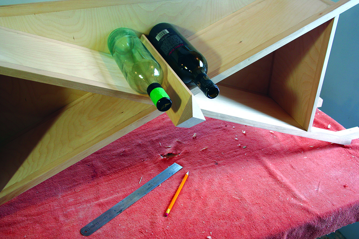
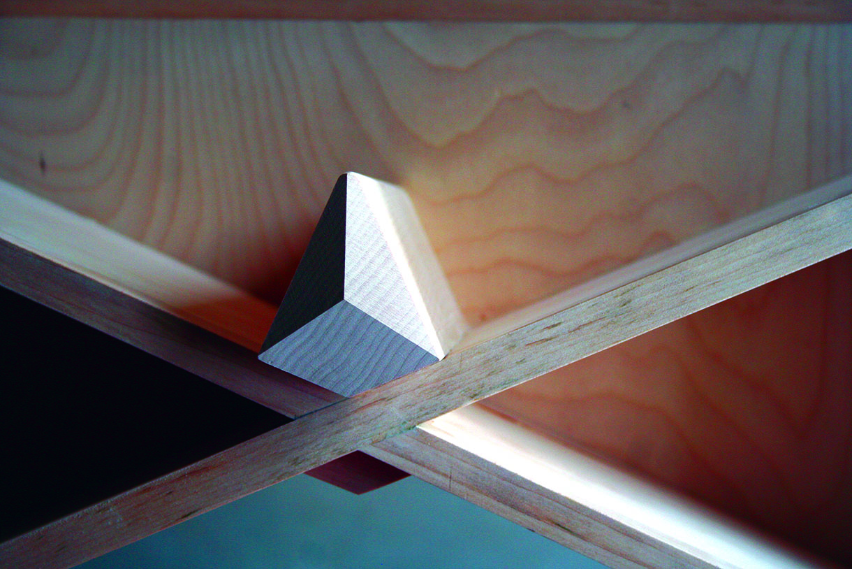
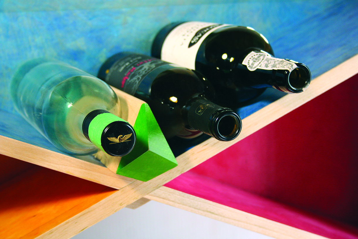
15. There is a specially designed feature at the centre of the X that stops the bottles from rolling to the centre. It also provides strength to the X frame and brings further visual interest. There are two screws holding this in place, fixed from the bottom. A smaller block hides the screws and gives the table a higher finish. The drawing shows a larger centre piece, but visually this appeared too heavy
Back to the lathe
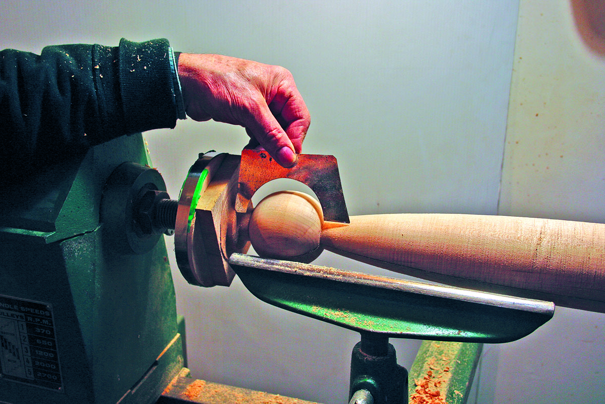
16. For the legs, a template was cut from a piece of sheet metal to form a semicircle
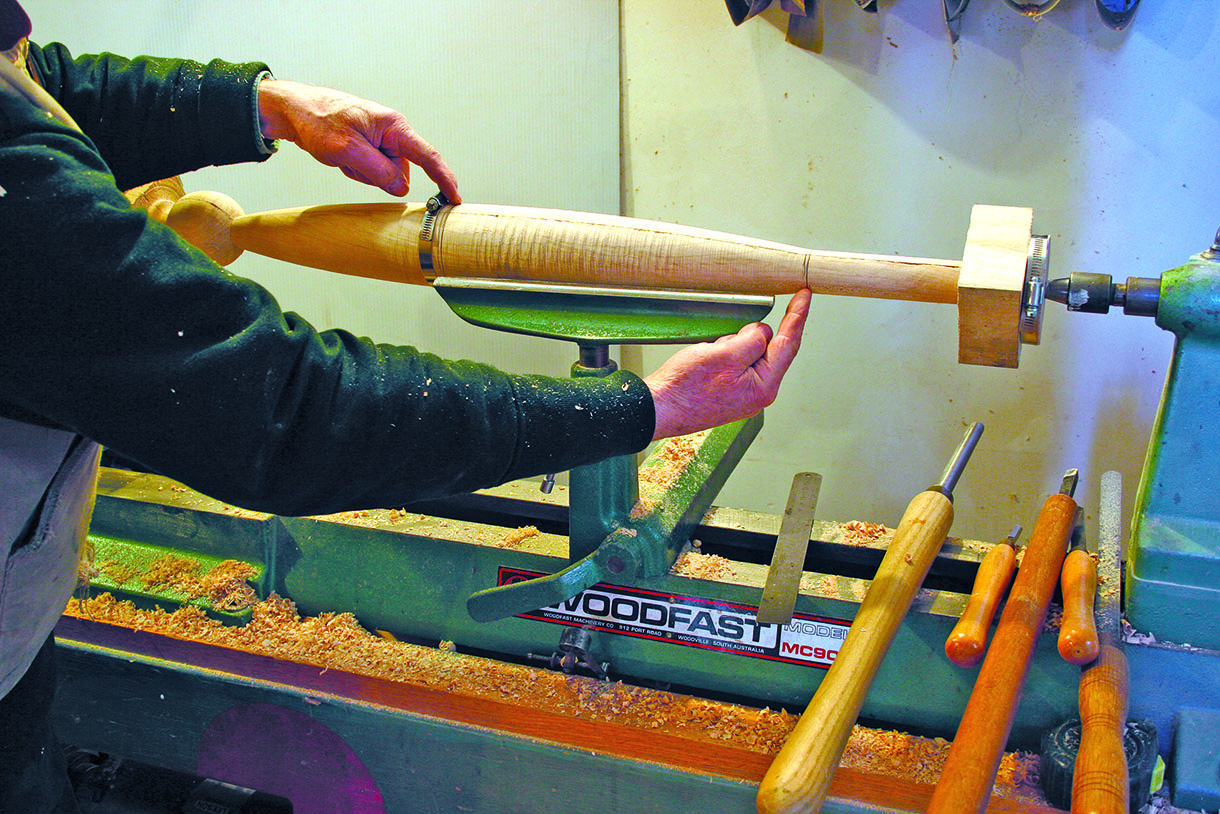
17. When the leg was on the lathe it looked OK, but it was essential to take it out and look at it in the vertical position. It was too close to symmetrical, which made the form look like it was sagging. The section between my fingers had to be slightly longer than the top section to prevent the sagging. Note the additional band clamp support at the centre. As the work is thinned the legs are prone to separating or gaping apart
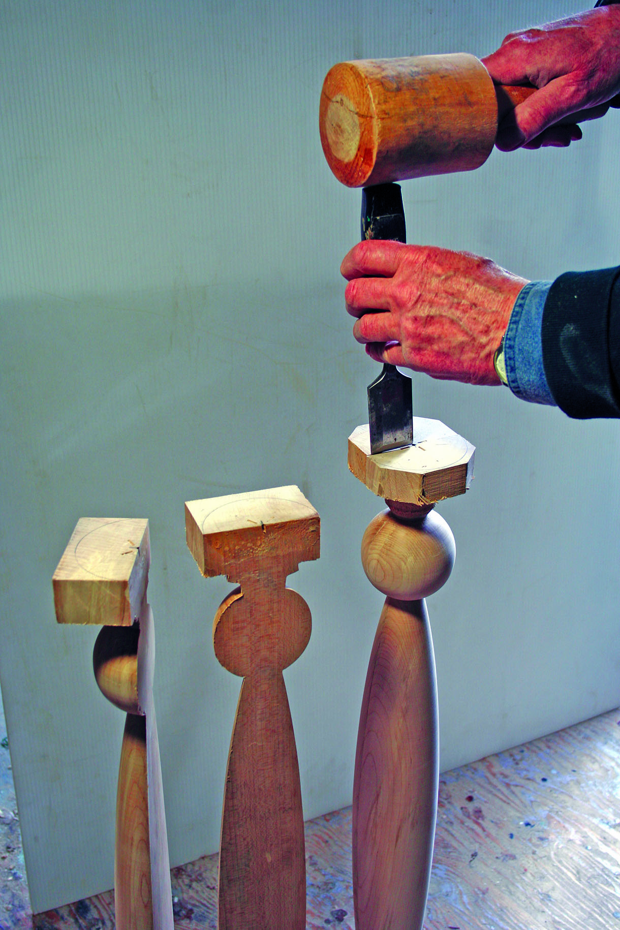
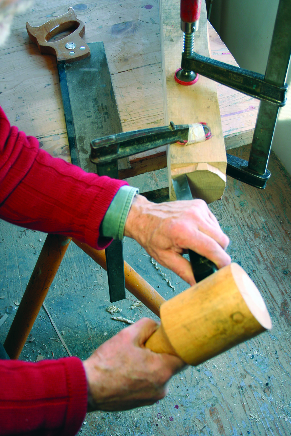
18. Having completed the turning and sanding while on the lathe, I stood the leg up and used a large chisel to split the turning apart
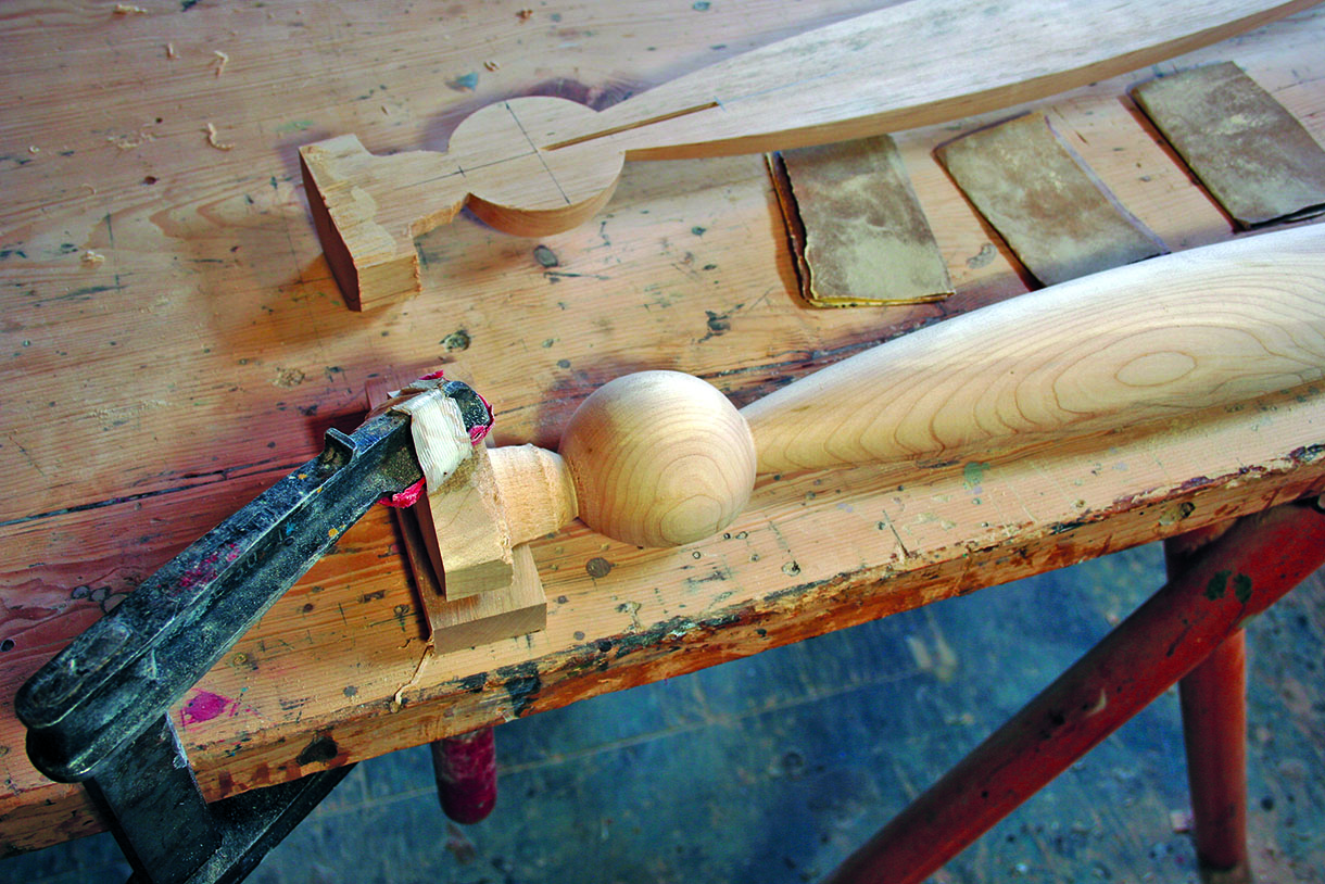
19. I kept the square blocks, or waste material, on the ends. These square blocks now become useful to clamp to the bench as they offer a square and true surface. I marked out where to place the rails
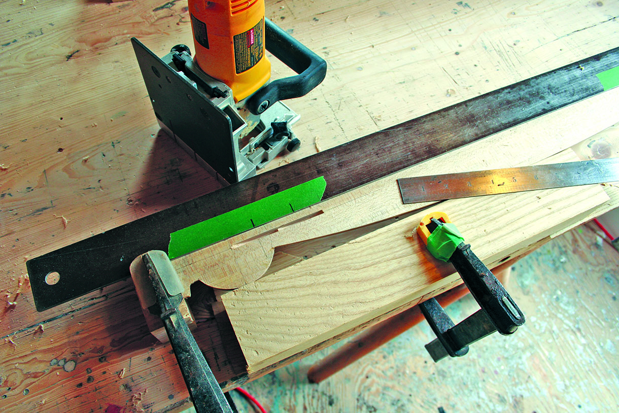
20. There are several ways to make the joinery for the rail to the leg. The setup shows marking out for the biscuit jointer. The larger top rail had two biscuits and the smaller lower rail had one biscuit
21. Before the glue up phase, it was important to ensure that all the surfaces were adequately finished with abrasives. A block was placed under the turning to enable sanding. Occasionally when turning the edge, the turnings may break away. This was the best time to fix any problems
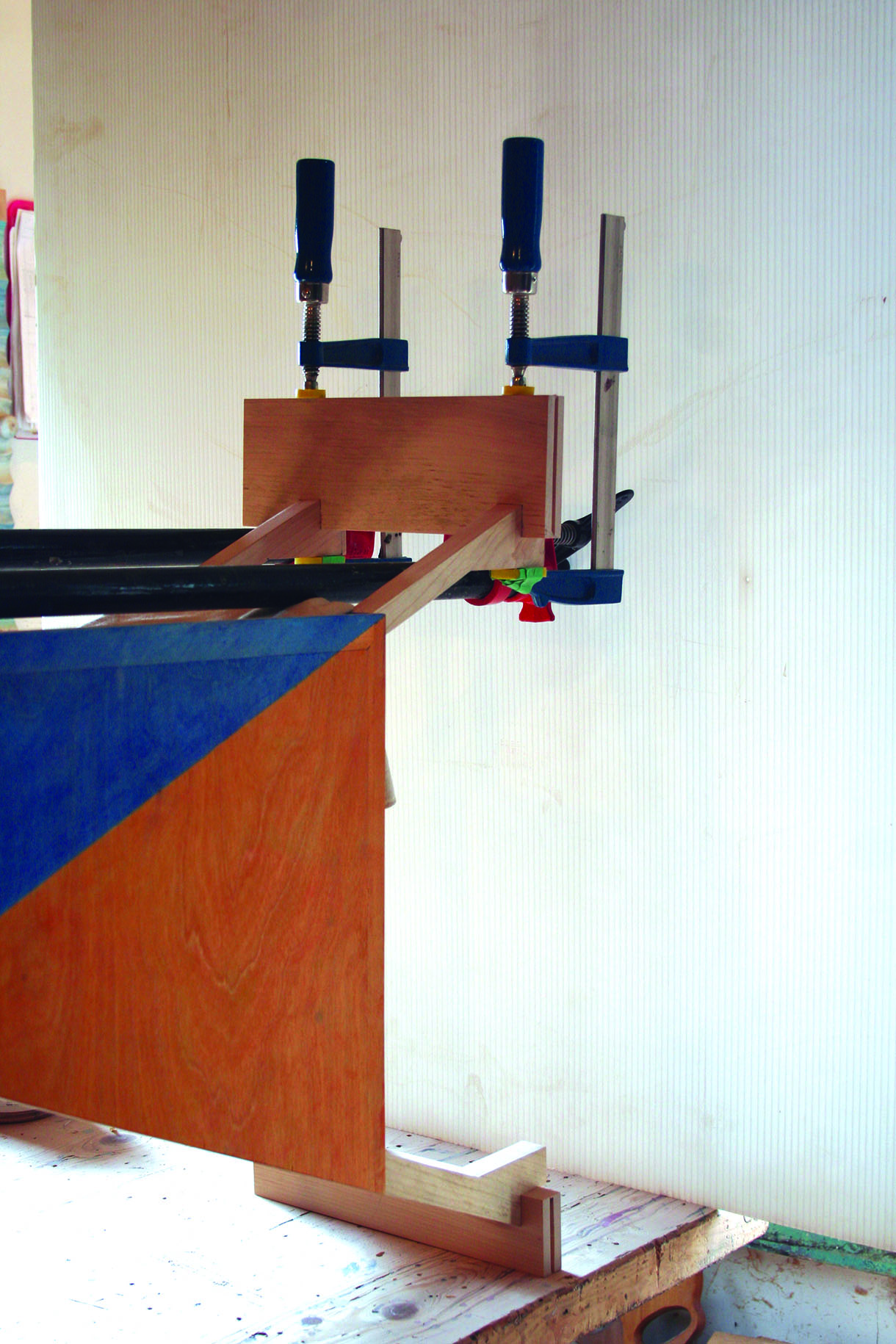
22. I glued the rails to the carcass X frame and then attached the legs. The biscuit joint does give the tolerances a chance to be plus or minus a hair or two. The X frame does have some flexibility when clamping the rail with the bar clamp. I had to take care not to distort and get the rails out of square alignment. I clamped on a spacing strip to make sure through measuring that distortion was not taking place
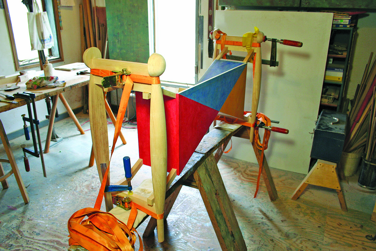
23. The legs were glued onto the rails of the X frame. Band clamps worked well for this. On one end, at the very last minute of gluing, I had to add a couple of C-clamps. A hairline crack in the joint needed to be coaxed away. The gluing was left overnight before removing the beads of glue around the joints. The X frame connection to the rails had a dowel drilled in after the gluing. This makes the connection and helps any short grain that may be structurally weaker. The dowel has a raised head to feature the connection. The table top was fitted to the frame. The top is made up from two ash boards and a strip of maple down the middle. The ash holds a rubbed stain in the open pores of the wood and the maple carves well with the milling machine. A simple cleat was used to fix the top in place. This method was in keeping and consistent with the rest of the design
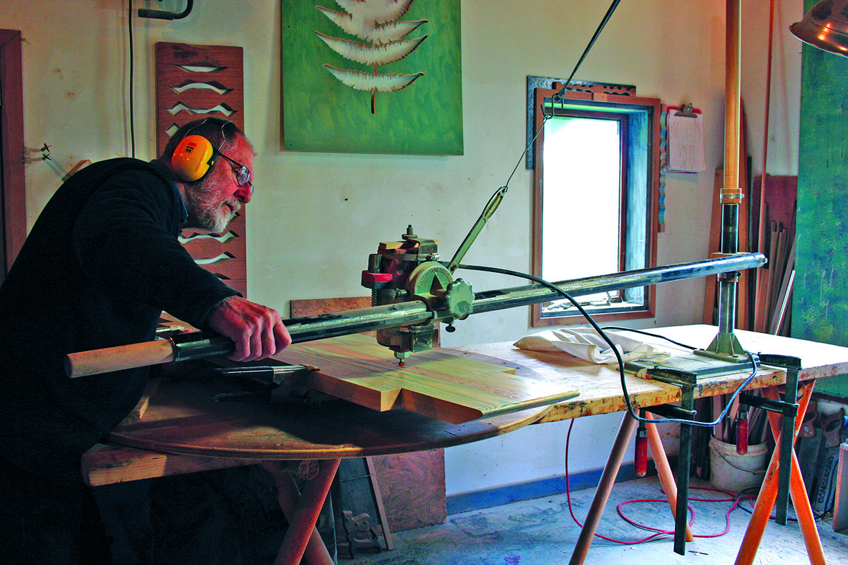
24. The first milling machine was made back in 1976. The milling machine shown is a smaller version, which is suitable for benchtop work. It has the potential of three axes when carving. This setup shows the arm with the router attached, hanging from a bungee cord. It allows a fingertip control and a nice fluid bounce for the router to carve the lines. The work is clamped on a turntable, which gives the milling machine the third axis it requires. This provides the potential to carve circles, spirals and fluid lines, reminiscent of rippling water
Surface detail
The table top was finished with urethane in which a pigment dye adds colour – see www.colorvie.com.
I started using this pigment system recently with great success. Before that I was using artist’s quality acrylic paints. Typically I will apply many coats, varying the colour with each layer to build up a depth of finish that is subtle, deep, rich and clearly done by hand. It looks great, with a nonindustrial aesthetic and an exceptionally hard finish.
 Now open a bottle of your favourite wine, pour a glass, stand back and enjoy the fruits of your labours.


