When Push Comes to Shove:
Derek Jones looks at using tabled lap joints
Derek Jones looks at using tabled lap joints
There’s not that much call for Japanese-style of joinery in my line of work, at least I’m not aware of ever consciously infusing a western style with an exotic influence. That said there are some obvious similarities between the styles; wedges, tenons, tapers and scarfs to name a few that make it impossible to completely separate the two.
Accepting that the basic rules of engagement for joining two or more pieces of material together with similar working properties are the same the world over, it’s interesting to note where and why things are done differently. Strip away the obvious cultural differences and you will find good solid practical reasons for the different approaches. The more intricate examples of Japanese joinery are linked to the design and construction of buildings and temples, the mechanics of which are dictated as much by the physical aspects of the material as the task of assembly. And let’s not forget that the origins of woodworking joinery are from a time when glues were either not available or just unsuited to the task. From a furniture maker’s perspective joinery that obviates the need for glue is an attractive one; no clamps, no downtime and no mess to clear up. What’s not to like? Add to the list of pros the idea of a convenient disassembly some time in the future and things start to look very attractive indeed.
Joints that meet this criteria are designed accordingly and use a variety of cunning tricks to make them work. The first step in planning such a joint is to recognise the stresses that will be applied to it such as compression, tension and deflection. Grain selection and orientation will typically be used to counter the primary force withat least one feature to locate things and another to lock the mating parts in place. Get the balance right and you have a joint with true structural integrity.
Of course, you could argue that when we construct a joint that uses glue, all these details have to be taken into consideration as well, along with appropriately aligned mating glue surfaces, which makes them even
more demanding. Following my attempt at this wedged lipped tabled lap joint, I’m not convinced.
Inspiration
The inspiration for trying this joint came from a traditional 19th-century Chinese chair. The back rail is made from three separate pieces of dense rosewood-like timber. This shape is not uncommon in the western world, Windsor chairs and Hans Wegner’s PP56/66 for example, and are mostly made from a single piece of wood. The piece in question, typically ash, would be subjected to heat and moisture in the form of steam rendering it pliable. While in this state the component would be forced into shape and held there until cool and dry thus retaining the shape. As clever as it is this technique won’t work on exotic timbers like rosewood hence the need for equally clever joinery.
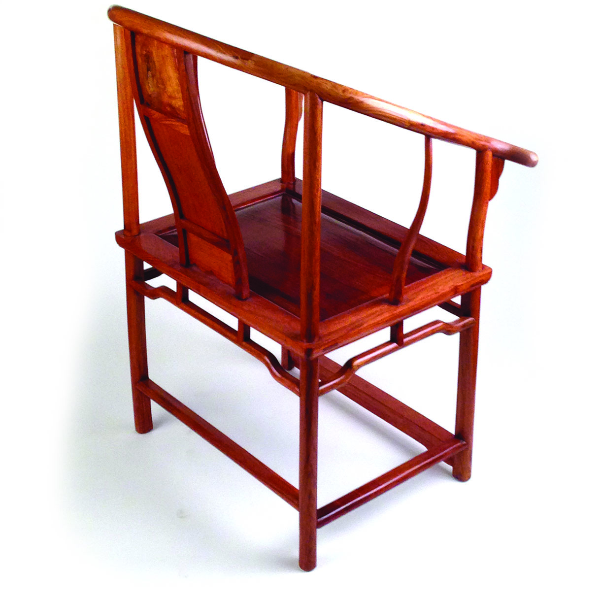
Three sections form the back rail on this Chinese chair
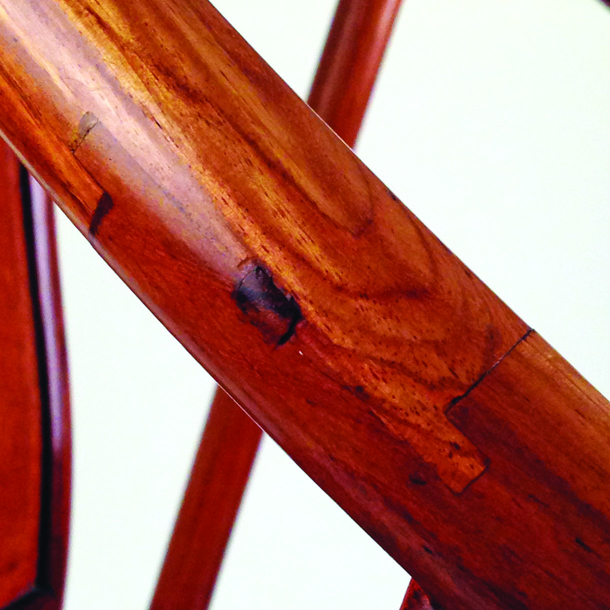
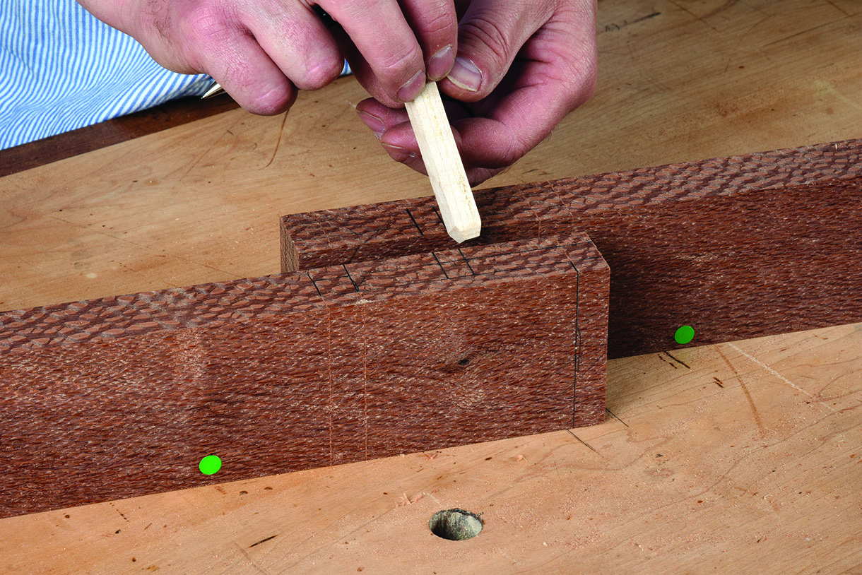
A peg forces the interlocking parts together
Designing the joint
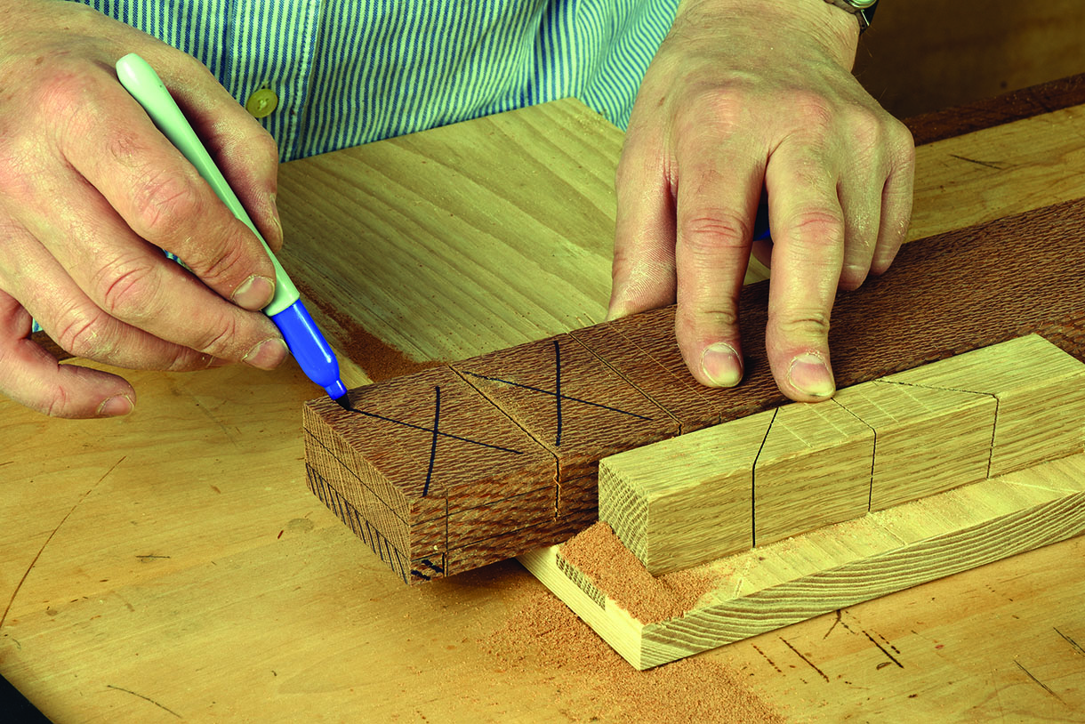
To familiarise myself with the general anatomy of the joint I made a sample from MDF. Although it won’t tell me anything about the strength of the joint apart from not being a suitable material it did help to identify some of the pitfalls in marking out. My choice of timber was a piece of Ropala that had been hanging around the workshop for years, which I immediately regretted. It’s as tough as old boots and doesn’t mark up as easily as something like mahogany. I’m pretty sure this is an easy trap to fall into as my approach to marking up was to adopt a very western style and proportion things out using the rule of thirds. I’ve since discovered an alternative technique that makes use of a Japanese square.
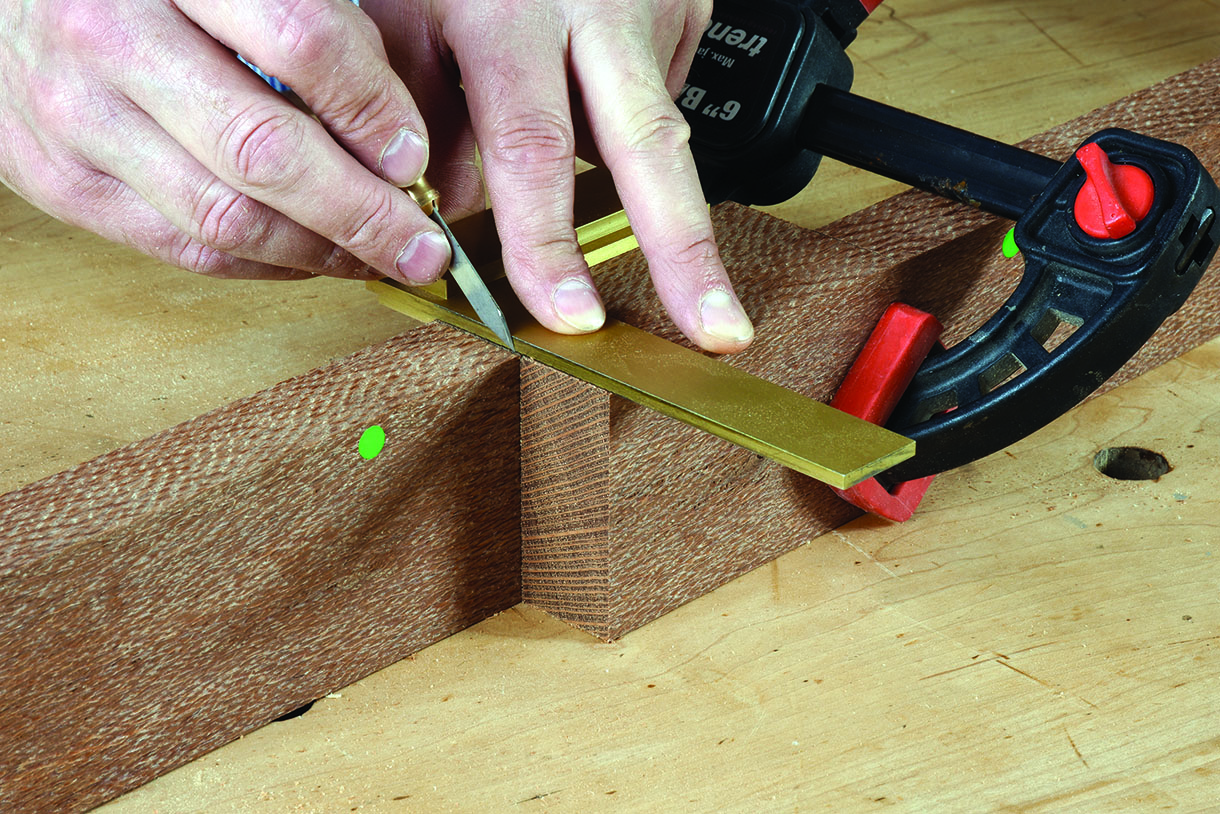
Components are often the most reliable method of transferring a dimension
Lay out the shoulder lines clearly and to depth
Lay out the shoulder lines clearly and to depth
Joint anatomy
Tabled joints feature a hook cut into the mating parts for alignment. In this joint ‘lap’ refers to each part of the joint overlapping the other. There is a lip at the end of each table to resist racking. The wedge or peg in this case is used to lock the parts in place.
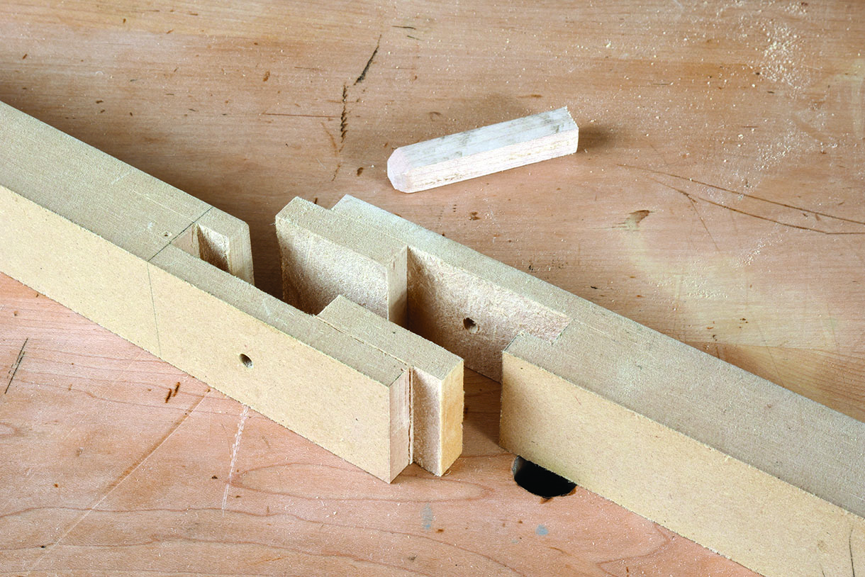
An MDF test piece shows all the major parts of the joint and how the voids are to be filled
Below the waste
This joint is made up of several straight saw cuts that mirror those used to create a straightforward tenon, i.e. shoulders and cheeks. I recommend zoning the waste sections above the base lines and marking them accordingly as the tables are created from within the component. Pay careful attention to the depth of the crosscuts as well as to which side of the line constitutes waste. Sounds obvious but it will catch you out if you’re not paying attention. If you’re geared up for western joinery then there are no special tools required to take on this joint. A sturdy shoulder plane will soon become your best friend closely followed by a wide chisel.
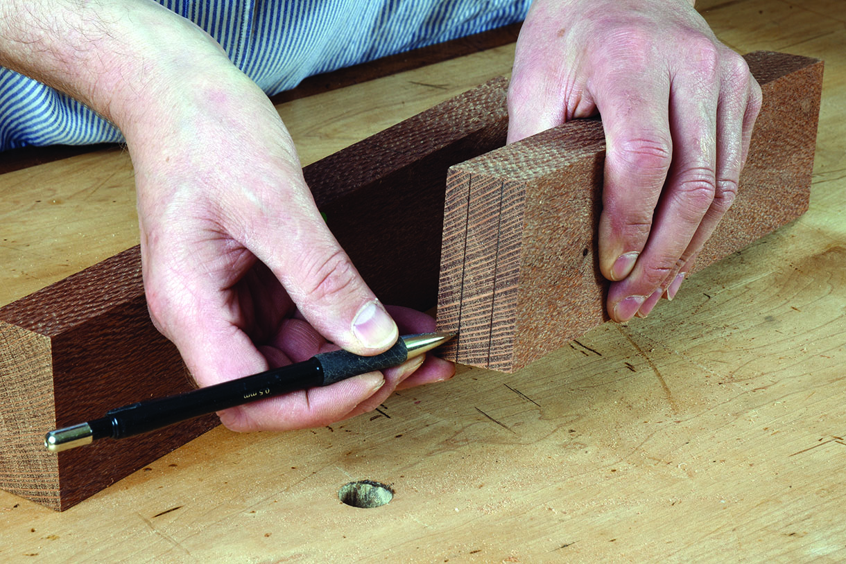
Identify waste clearly
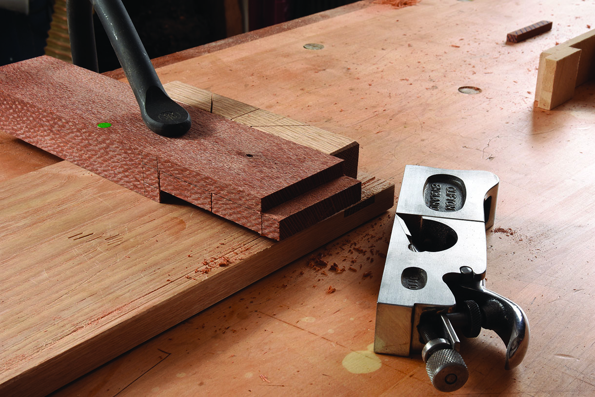
Unless you class a shoulder plane as a specialist tool no specialist tools are required
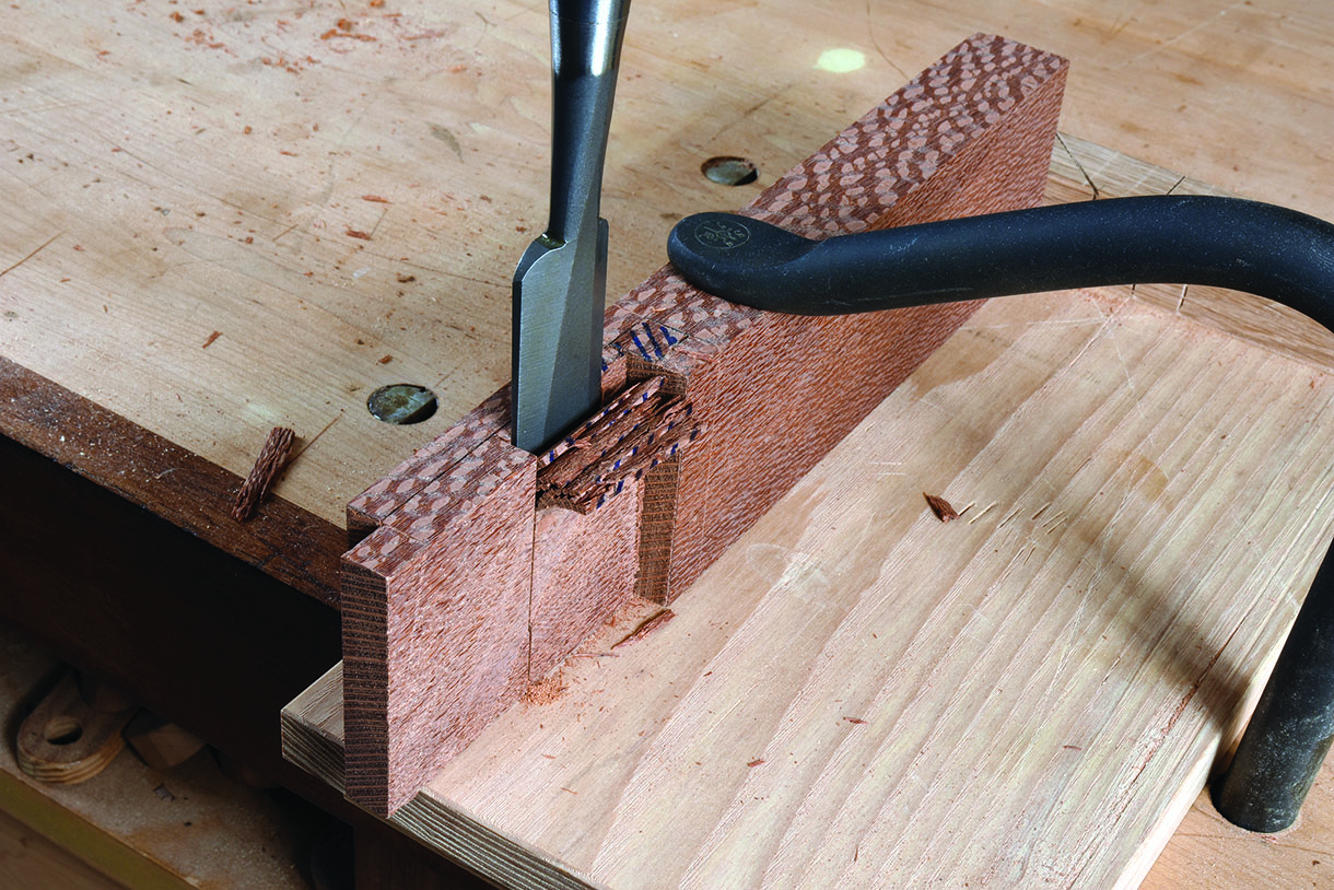
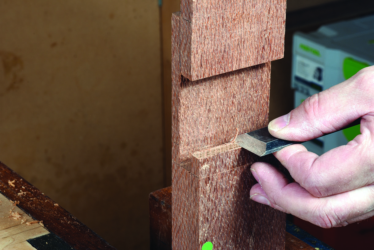
A wide chisel is the way to go…
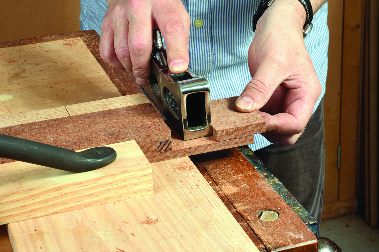
… followed by a wide shoulder plane
Mark two
Not all of your cut lines can be marked out from the outset. The channels for the lips, for example, can only be made after the tables have been cut if you adopt the thirds rule and keep all the different elements the same thickness. Sawing the waste out for the channel also represents a challenge. A frame saw worked well
on this occasion but there’s no substitute for planning your joinery to suit your tools in the first place. Increasing the width of the tables would have allowed me to drop in a small dovetail saw. In hindsight I think I could also have made this deep cheek cut to the full depth of the channel in line with the face of the table and made thicker lips.
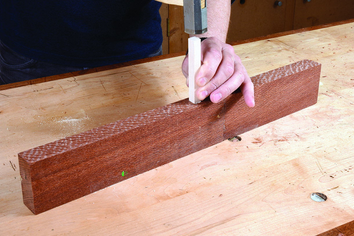
You’ll have to gauge up twice so make sure you have a gauge that can get into tight spaces
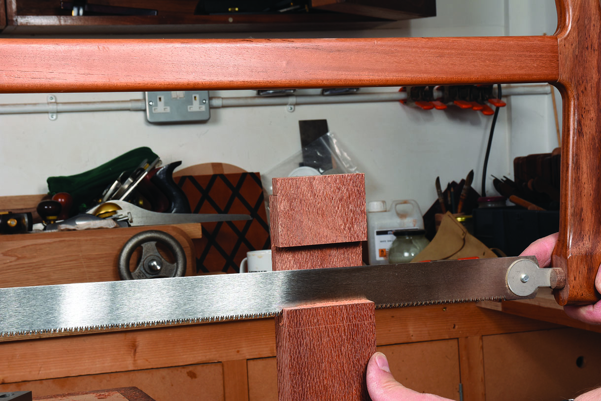
You don’t have to use a frame saw to cut the chanel but it’s quicker if you do
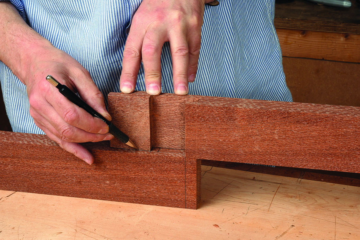
Outline the waste for the mating part from the first half of the joint to avoid any mistakes
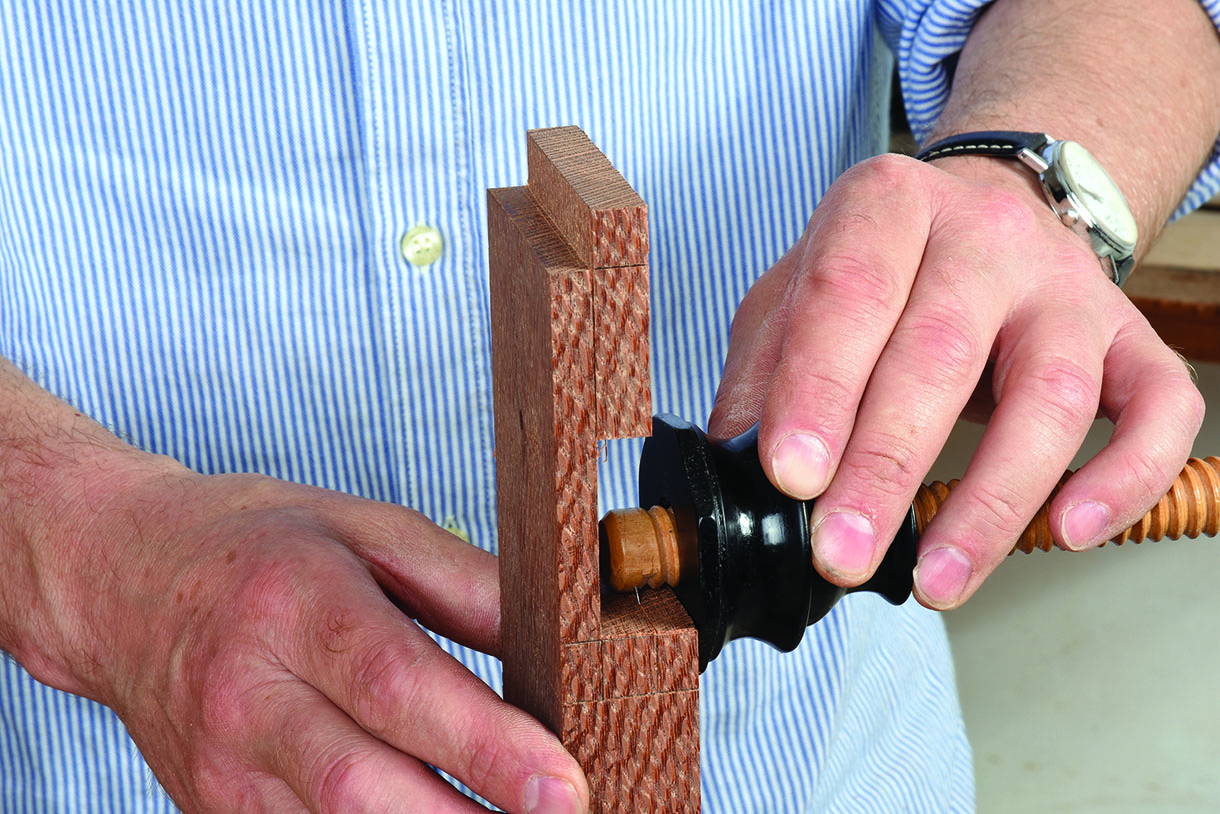
Closing the gap
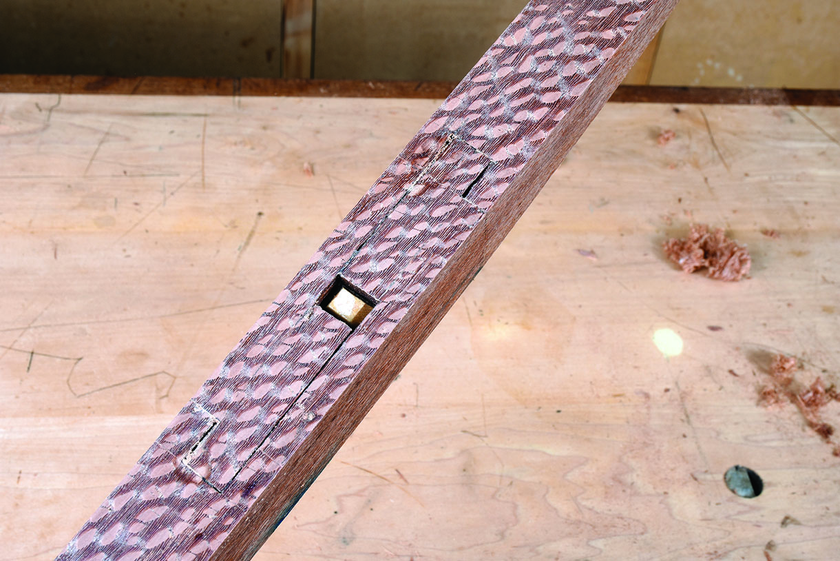
To fine tune the joint assemble the components with a temporary peg or with a sash clamp. Run a saw partway down the shoulder lines and take the joint apart. You should now have a small amount of waste that can be removed with a chisel to the thickness of the kerf. You’re now free to shoot the ends of the lips to match. When you’re happy with the fit add glue if you wish (I did) and drive the wedge in without glue, also if you wish (I did).
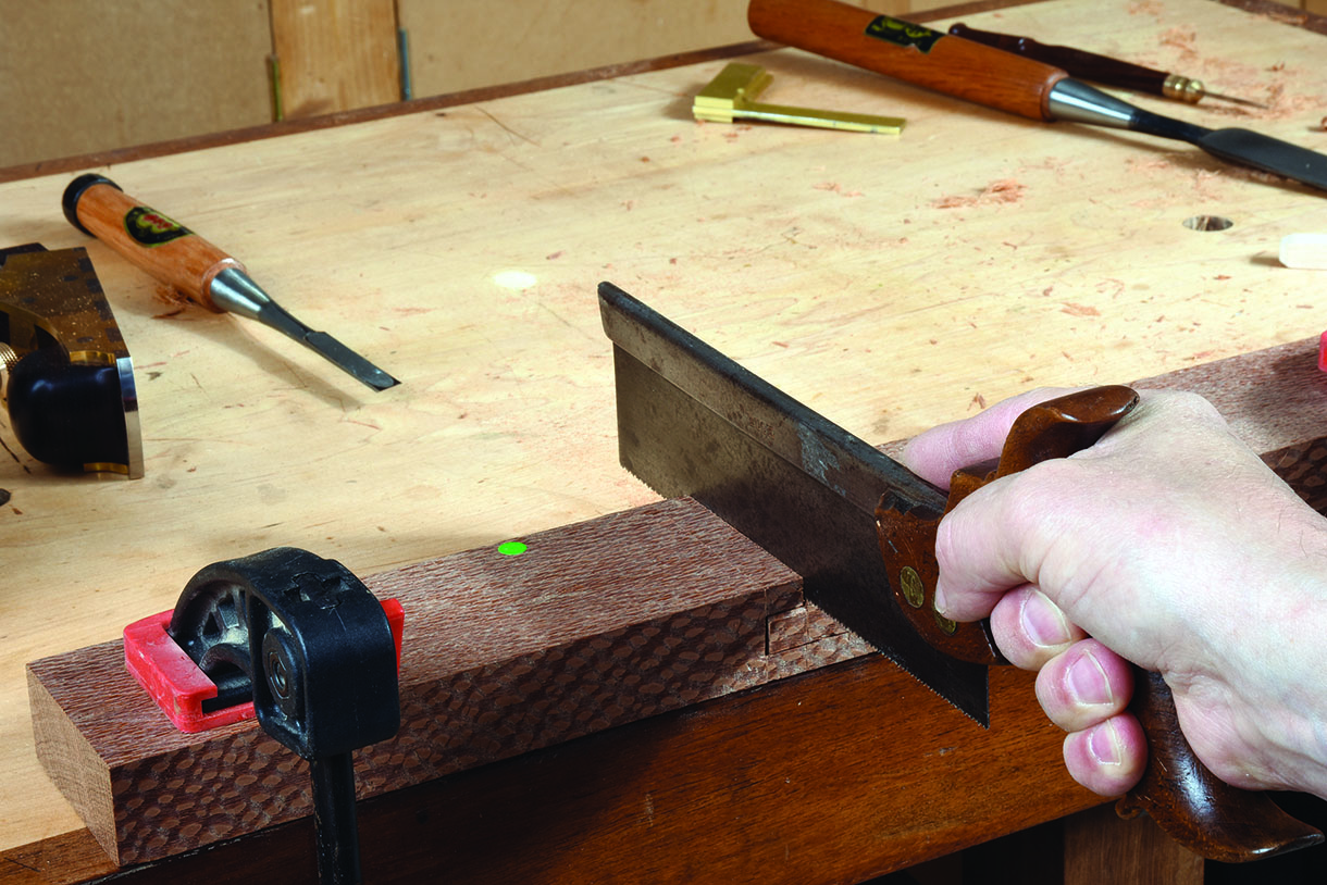
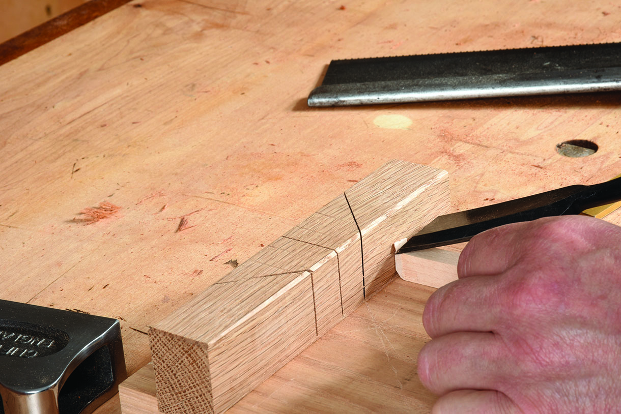
Cut partway through the joint line
Remove the waste with a chisel
Drive the wedge in to complete the joint
About wedges
There are two main things to bear in mind when making wedges. First, because wood consists of a tubular cell structure it can resist great compression loads along the direction of the grain without the fibres being destroyed. So rather than search in the bin for a wedge shaped offcut select your wedges with the straightest grain possible just as if you were choosing timber for a set of chair legs. The second point and probably the more important of the two is to only select dry wood and here’s why. Resistance to compression perpendicular to the grain is less than that previously mentioned and because wedges are typically driven into the joint close to right angles to the grain of the mating parts they are exposed to lateral compression. As the wood dries it shrinks and as shrinking under compression damages the cell structure the wedges can no longer do their job.
Chamfer the tip of the wedge to keep it on track
Shaping up
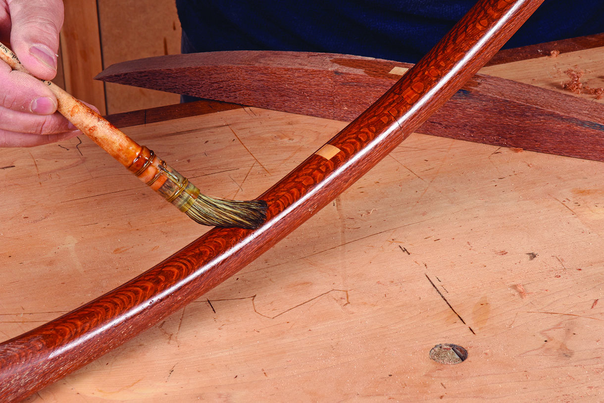
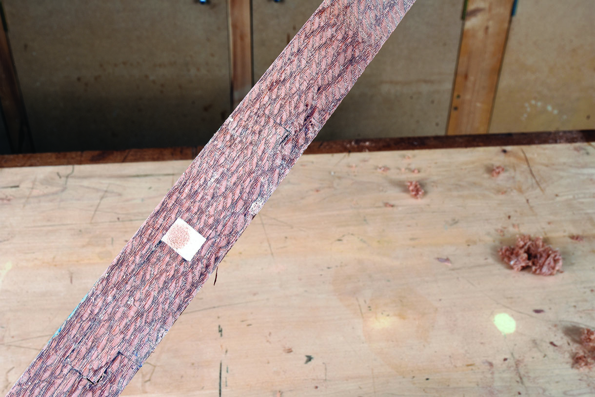
To replicate the chair back component I decided to shape the joint and started with a single curve using one of Sterling Tool Works stainless steel French curves as a template. Not having access to a shave horse in the workshop I held onto as much of the board as possible while using a succession of rasp, spoke shave and scraper to round things off before applying a little shellac. The overall result was quite satisfying.
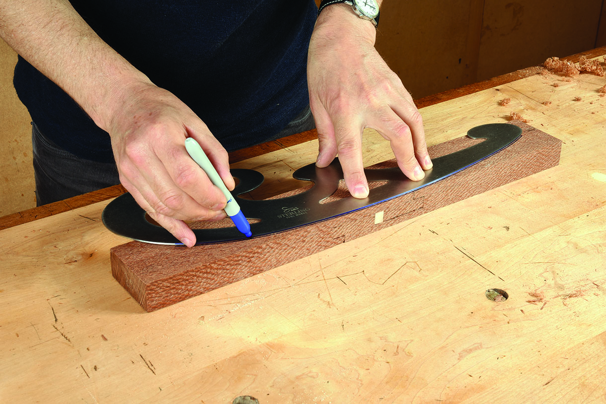
French curves are great tools to have around the workshop for all manner of impromptu prototyping
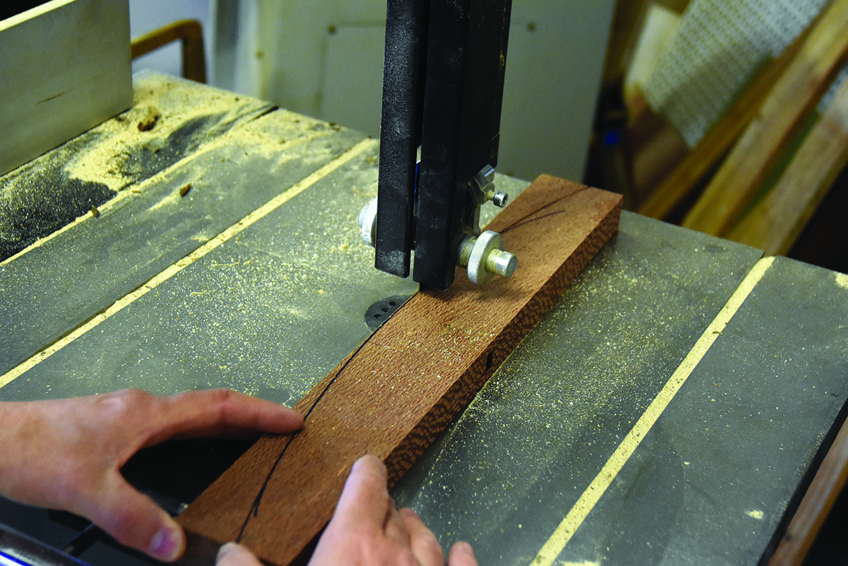
Leave as much material in tact as you can while shaping
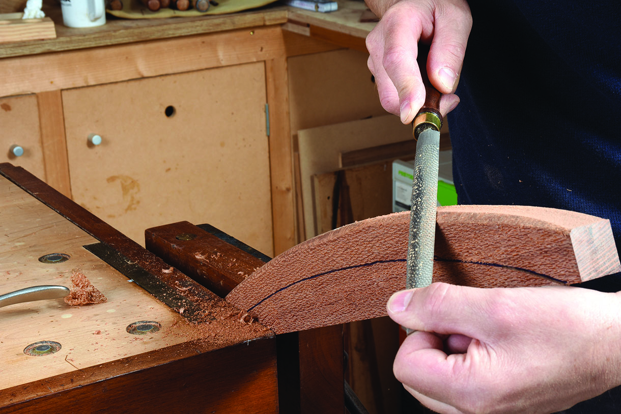
A coarse rasp removes material quickly and doesn’t need sharpening
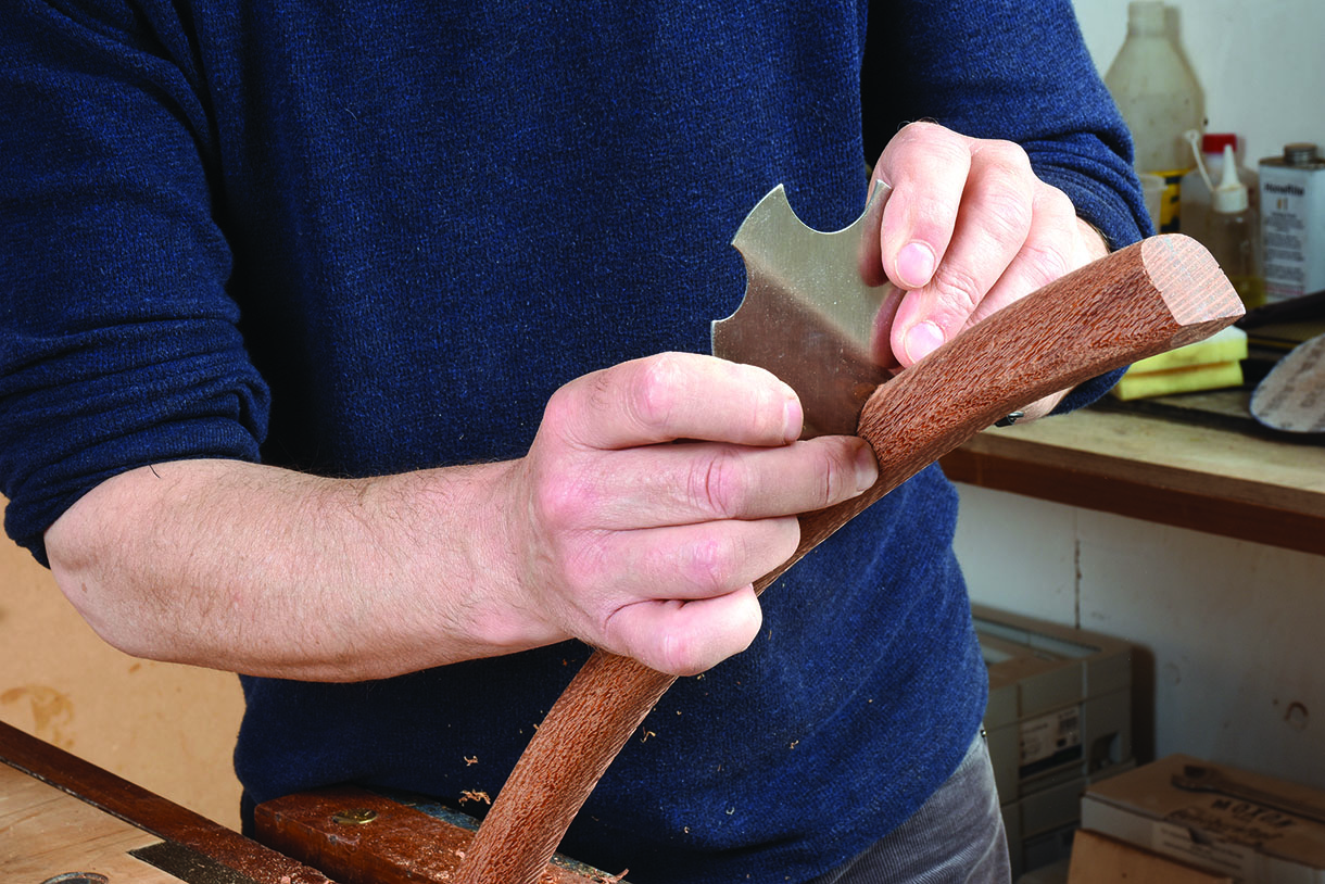
For a consistent profile try shaped scrapers
Think inside the box
All that cross grain planing and shooting while making the joint resulted in a lot of tear-out along the edge of my knife marks. There are ways to avoid this of course, such as planing from both directions or using a spelch block, but as I knew this material was destined for the scrap pile I focussed my attention on creating a tight joint in the middle of the block. It worked and was a good exercise in levelling areas that aren’t visible until it’s too late. So would I consider using this joint in future? Sure. Would I do it differently? Absolutely and that’s half the fun.
Lots of tear-out on the outer edges
Nice tight edges on the inside
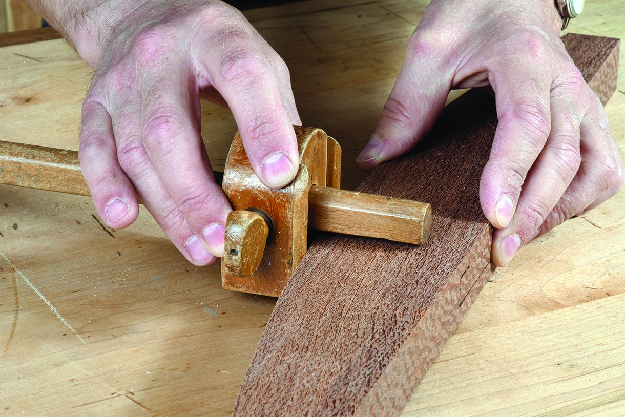
2 for 1 marking gauge
You can convert a cheap wooden marking gauge to mark a line at a consisten distance from a curved edge by gluing a couple of half round blocks of hardwood to the back side of the headstock and threading it onto the other end of the beam. The two bars and pin are now fixed in a triangulation point, an Isosceles triangle to be precise, so you need to ensure the blocks maintain constant contact with the edge of the workpiece.
It works on concave and convex curves of a single radius. You can expect a slight deviation when following small ovals, elipses or other complex shapes but for the most part the difference is hard to spot.