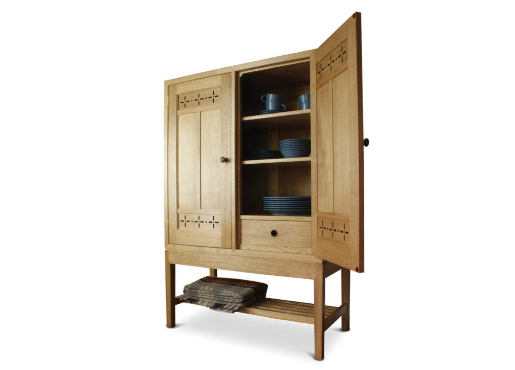
Martin Harvey explains how he developed the key features of his crockery cabinet
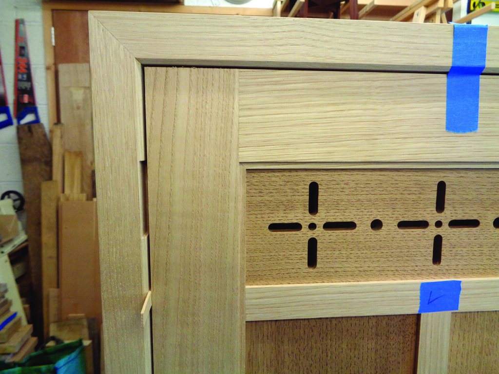
When I started out wanting to be a furniture designer-maker I spent several periods of employment with established local cabinetmakers in an effort to better understand the everyday demands of working within a commercial environment. For one of my first projects I was handed a pile of jigs and sent off to make 15 American red oak cooker canopies. The main feature of the canopies was a decorative pierced fretwork panel that ran across the front of the hood. Routing the fretwork from a simple pattern proved a relatively easy technique to master and the end result turned out to be quite effective. I bookmarked this process
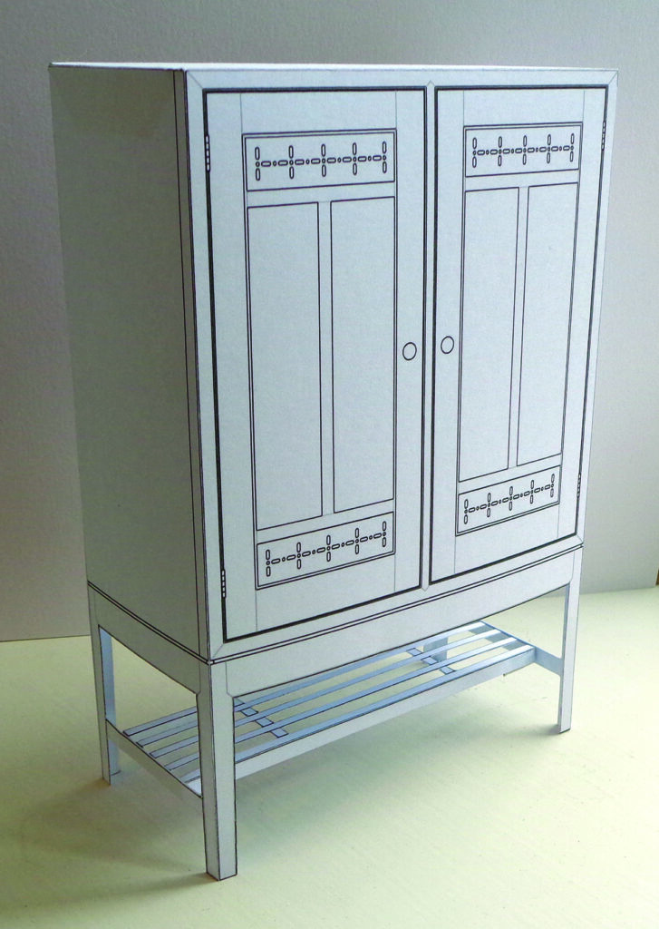
as something to one day develop and incorporate within my own work. The idea behind my crockery cabinet was to create a piece of furniture that links the kitchen and the dining room. Having spent several periods designing and making bespoke kitchens I believe that this is one area where customers feel comfortable investing in high-end cabinetry. This cabinet is my attempt to access the peripheries of the lucrative bespoke kitchen market. The crockery cabinet was of a manageable size to make in my small one-man shop and a project that finally gave me the opportunity to produce some more pierced fretwork panels.
Drawing
Resolving the pattern
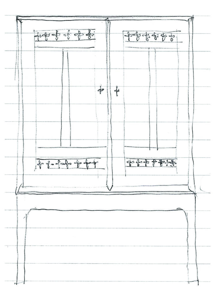
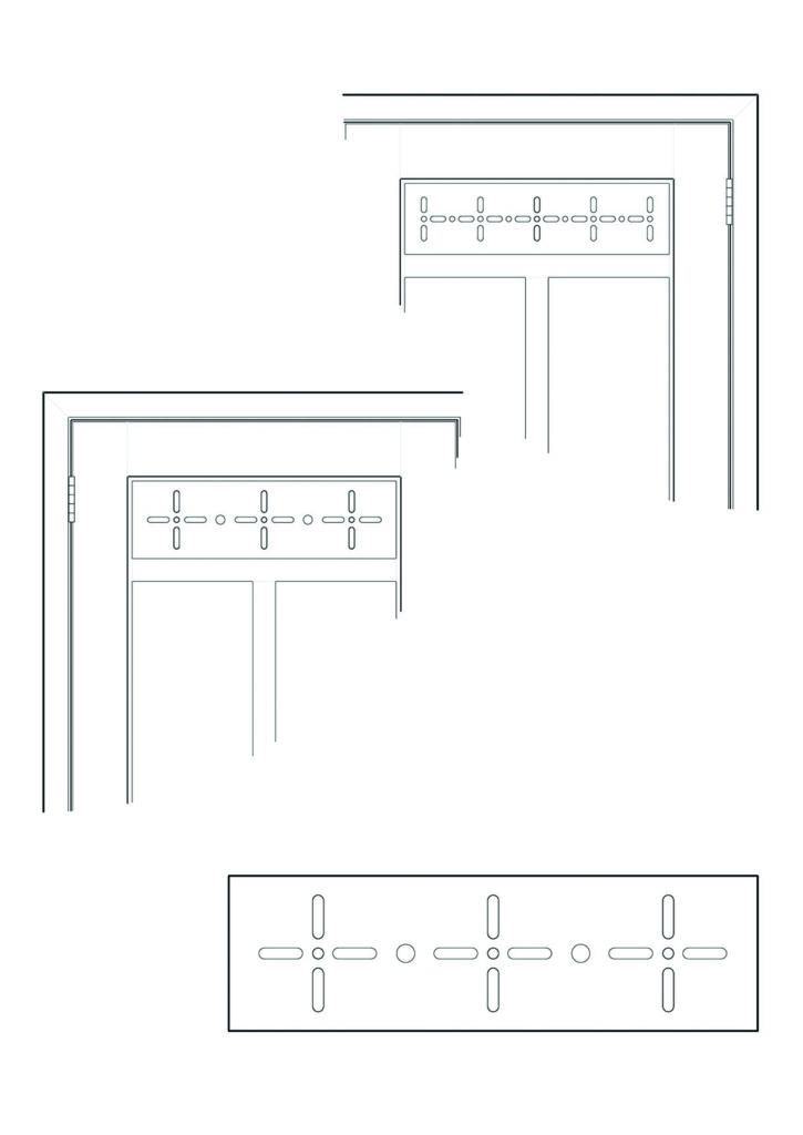
My process when developing a piece of furniture usually begins with a series of simple notes and sketches as I try to find a starting point. Once I have a vague idea of where I am heading I begin drawing up the design to scale in two dimensions. From this initial drawing I take a copy of the elevations, print them out on to some thick paper and stick them all together to make a quick scaled model. I put this model to one side and live with it for a couple of days, reassessing the design with fresh eyes until I am happy. On this occasion I felt that my original layout for the piercing on the door panels was a bit cluttered so went back to the drawing to adjust the spacing. Usually at this point I would produce a full scale drawing on a sheet of hardboard to get a feel for how the design works at human scale but in this instance I was happy to move forward with the build.
Pierced panel jig
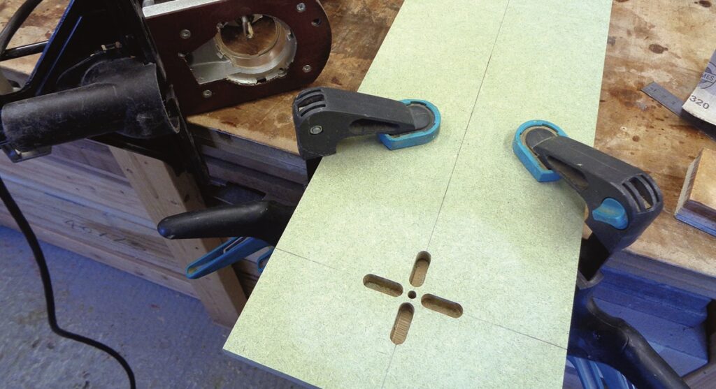
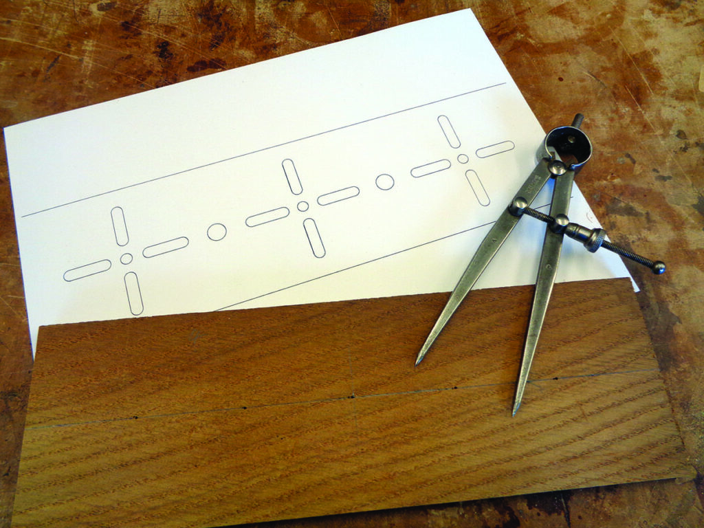
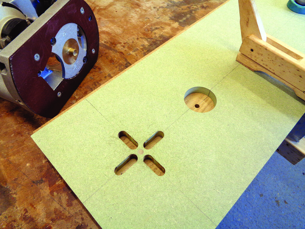
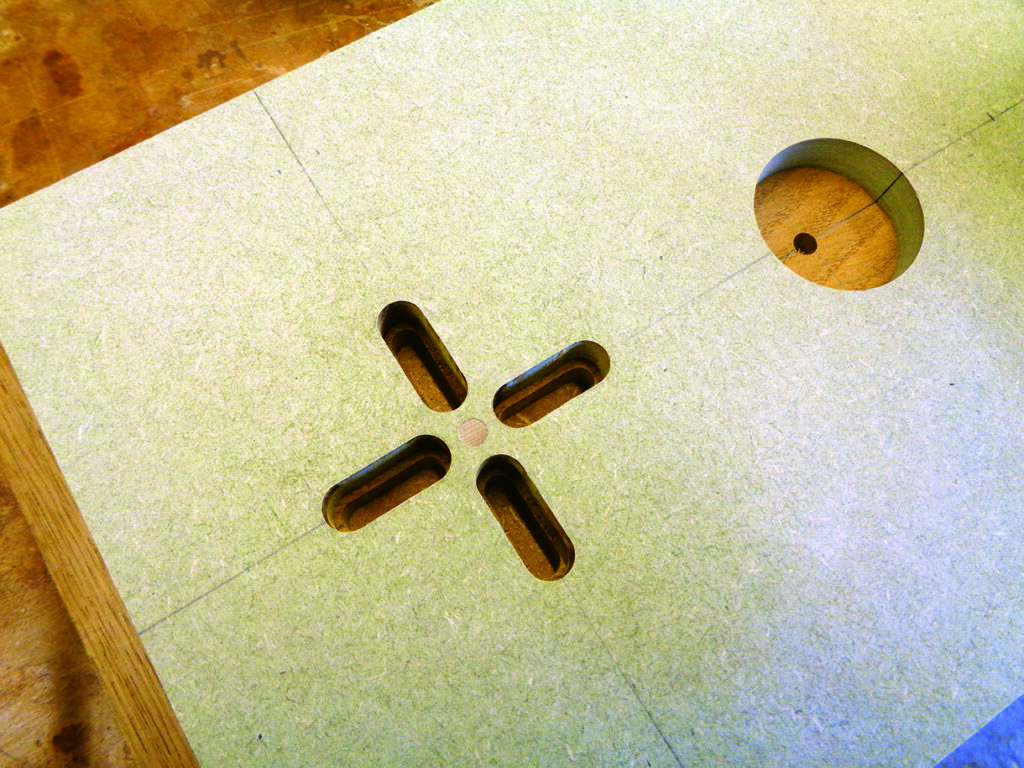
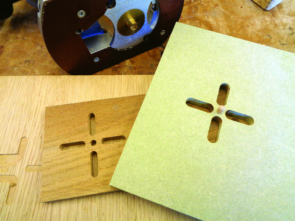
To create the pierced panels on the cabinet doors I decided to make a simple router jig similar to the one I used on the cooker canopies. Of course this could easily be done on a CNC router if you have access to one but without this facility and not wanting the hassle of outsourcing to others, the preference was to maintain full control and do it myself. To make the jig I cut a piece of MDF, making sure it was long enough to provide a good clamping surface and wide enough to support the base of my router. I used 12mm for this because my guidebush is 9mm long and it needs to stay within the thickness of the board. I drew a line down the centre of the jig and picked a point to mark the middle of the pattern with a cross. At this point I drilled a 6mm hole to accept a standard dowel that will locate the jig on the pierced panel. The elongated cross holes on the pattern are all 24mm long by 6mm wide so I marked the centre of each on my cross lines and measured out 14mm either side allowing for the 2mm offset of a 10mm guidebush. With the pattern all marked out I attached the router’s parallel side fence and with a 10mm router bit cut the pattern using the edges of the jig as my guide. Accuracy is paramount here with each cut needing to be dead centre and to stop at the correct length. To align the jig I cut a peep hole and marked the centre line down the walls of the hole. The dowel location peg can now be fitted in the 6mm hole and the jig is ready to use.
Using the jig
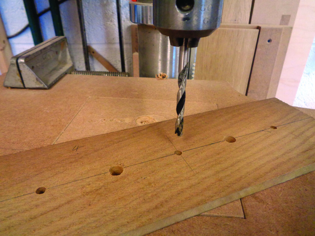
To test the jig, I made up a sample panel cut to the same dimensions needed for the doors. I drew a centre line down the face of the panel and marked out the positions for the holes spaced at 48mm centres. The holes were bored on the drill press using 6mm and 9mm lip and spur bits. To use the jig I located the dowel peg in
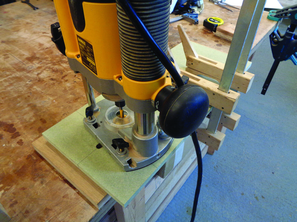
each appropriate hole on the panel and lined it up with the centre line through the peep hole, clamping the whole assembly to my bench with a sacrificial backing board to protect the bench and stop blowout on the back of the panel. The pattern was routed with a 6mm bit through the 10mm guidebush. For a clean cut I used the highest speed, a sharp bit and plunged in three stages through the 9mm panel. More importantly I found the need for good extraction to clear the cut and allow the guidebush to run freely in the pattern. Once I had completed the test panel and felt happy with the result, I moved on to repeat the process for the cabinet doors.
Doubling the detail
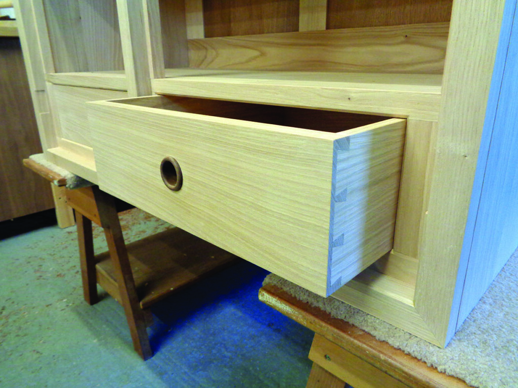
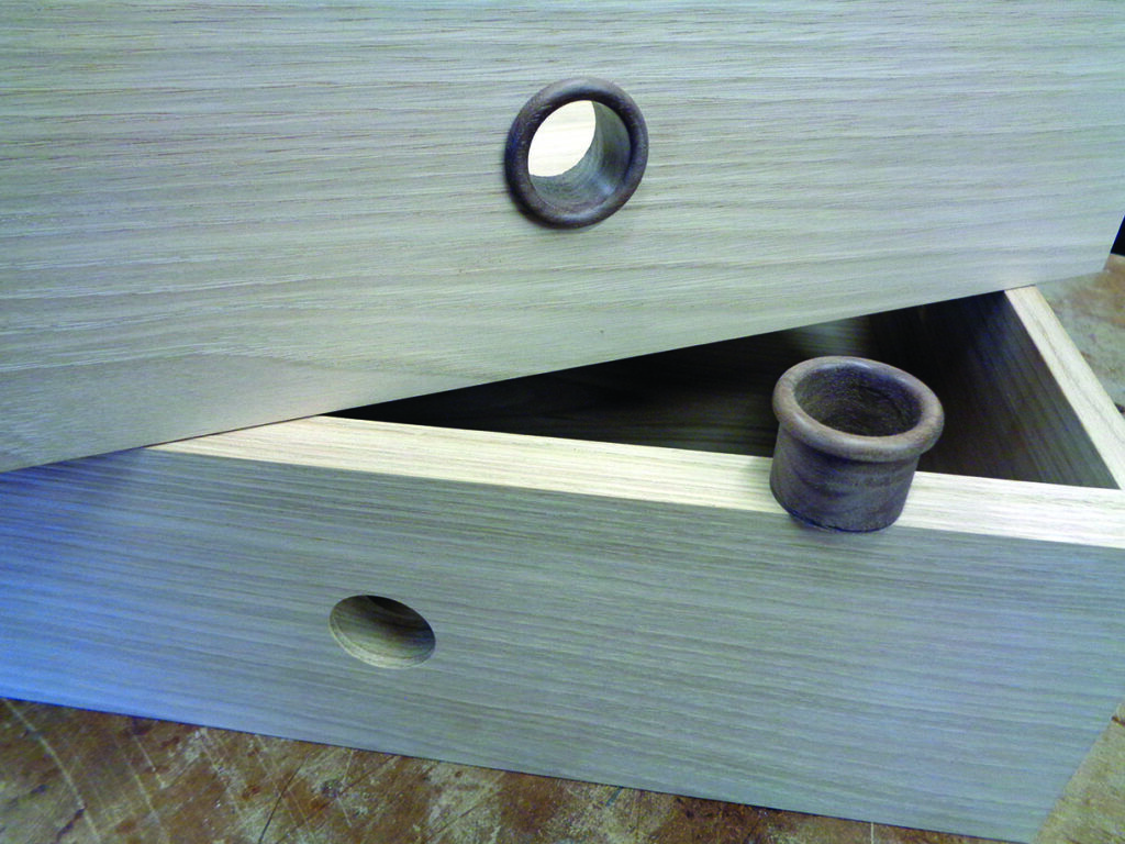
The doors of the cabinet were set back 3mm within a face frame which was chamfered all around its inside edges to add visual depth and texture to the cabinet fascia. The chamfer detail was carried on down through the inside edges of the base and when the doors were open I used the same detail on the frame around the drawers. Initially I was planning to bore some simple holes for finger pulls on the drawer fronts in direct relation to the piercing on the doors. On reflection I decided to use the extra depth gained by the chamfer and the set-back drawer fronts to add a raised finger pull detail in a contrasting timber to draw the eye to the point of use. I chose American black walnut for the finger inserts because it contrasted well with the sweet chestnut in both colour and grain structure. The tighter grain of the walnut with a smoother finish feels good to touch and I repeated this detail with simple turned walnut knobs on the front of the doors.
Finger pull inserts
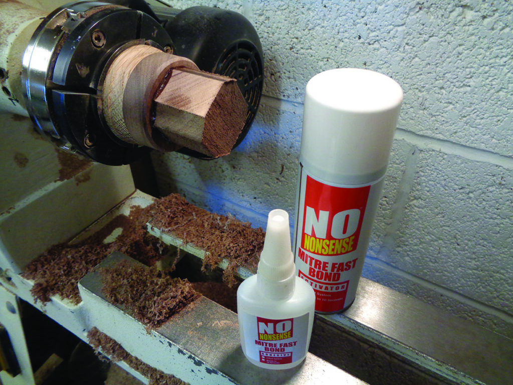
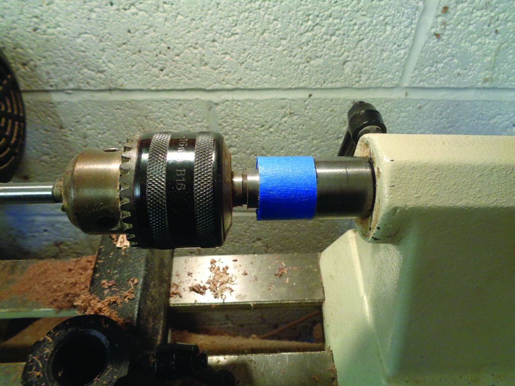
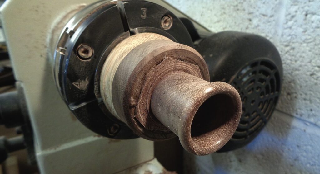
To make the finger pull inserts I turned to the lathe and threaded a sacrificial blank on to my auxiliary screw chuck. I squared up the face and used some superglue to quickly attach the walnut blank for the insert. The blank was reduced to 35mm diameter and the front face squared off cutting a small V indent at the centre to guide the point of a Forstner bit. Measuring back 3mm from the front face, I reduced the rest of the insert to 30mm leaving a 2.5mm shoulder and then bored out the centre with a 25mm Forstner bit. Cutting this hole only left a wall thickness of 2.5mm and on my first attempt I was too aggressive with the lathe running too fast. The heat generated by the friction of the bit caused the thin timber wall to fracture so on my next attempt I resharpened the bit and reduced the speed, leaving a very clean cut. The drawer fronts were 20mm thick so I gauged the depth of the hole to 25mm using some blue tape on the shaft of the chuck, winding it out 25mm and marking this point to indicating when to stop. This left a good glued surface to hold the insert and prevented me from running in to the sacrificial blank that was needed for the next insert. I rounded over the rim of the insert with a 2.5mm radius and parted the component off the lathe. After cleaning up the face of the sacrificial blank it was just a case of repeating this procedure.
Drawers
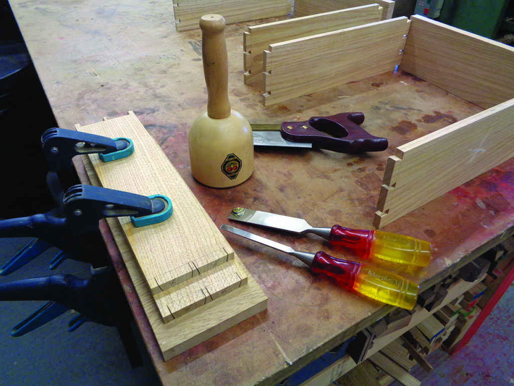
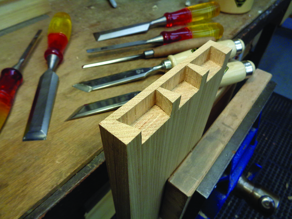
For the crockery cabinet drawers I used lapped dovetails on the front and through dovetails at the rear with solid sweet chestnut bottoms running under the backboard allowing for seasonal movement. As this is a practical piece, I used 12mm stock on the sides and back, 9mm for the bottom and 20mm drawer fronts, which gives a healthy amount of material to endure a harder life. I cut the tails first and then the pins before running the front and sides over a tablesaw blade taking multiple cuts to clear a groove for my bottom panels. I like to cut the groove this way because I find it a quick and precise method for gauging the width of the groove
to the exact thickness of the panel. To make waste removal from the pin sockets a little easier I use a pair of left and right skew chisels that are great for cleaning out the awkward corners.
Prior to assembling the drawers I prepared the 30mm holes in the drawer fronts to accept the finger pull inserts and, once glued-up, went about fine fitting the drawers to the cabinet. After cleaning up the drawers and lightly relieving the edges with some 320-grit abrasive the last step was to glue in the inserts. To avoid
any glue or moisture getting on the front face of the drawer I took a fine brush and carefully painted a thin film of glue on the inside of the hole. I then painted a thin film around the leading third of the insert so that when I pushed the insert into the hole any excess glue on the side walls pushed out the bottom and any excess on the insert didn’t make it to the top leaving a good clean fascia. After levelling off the back face and taking the sharpness off the inside edge, the drawers were complete.
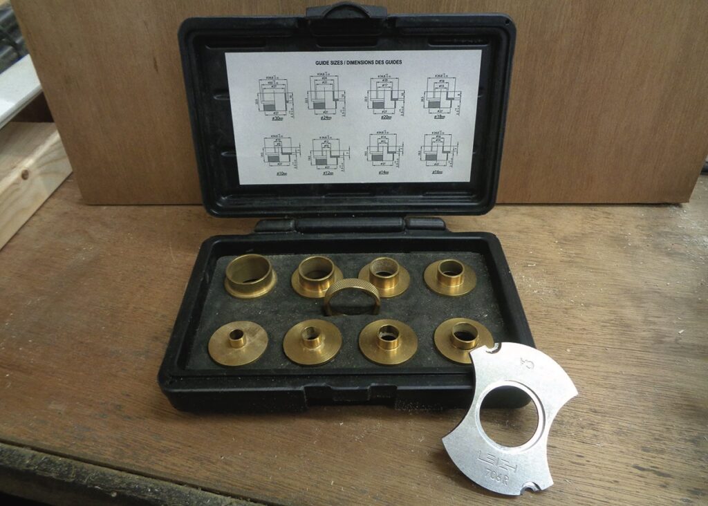
UJK threaded guidebush set
If you’re lucky, your router will have come with a token guidebush. This can be useful but limited in the fact
that you usually only get one size. If you are interested in routing and jig making I would highly recommend
the UJK threaded guidebush set. This set contains eight different sizes ranging from 10–30mm and is an extremely high quality product made in brass and housed in a useful plastic case. I purchased mine several years ago along with some Leigh guidebush adapters to fit my different routers. They have been a great investment and will expand your possibilities for jig making and help increase your levels of accuracy. I use mine all the time.
Base construction
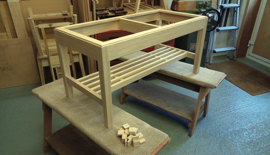
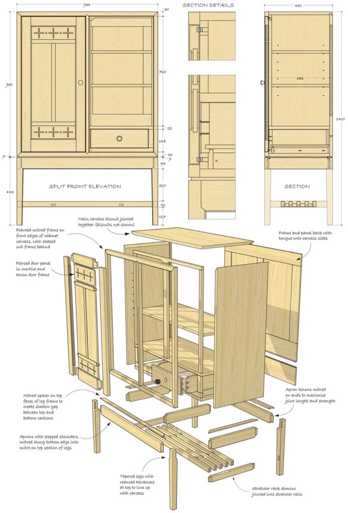
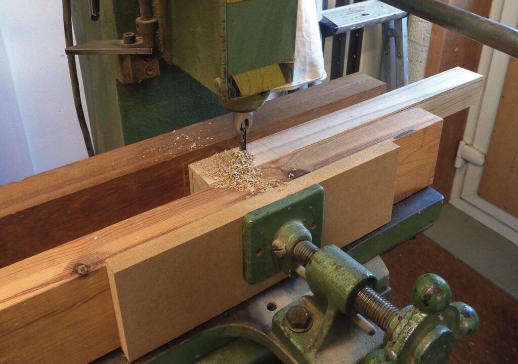
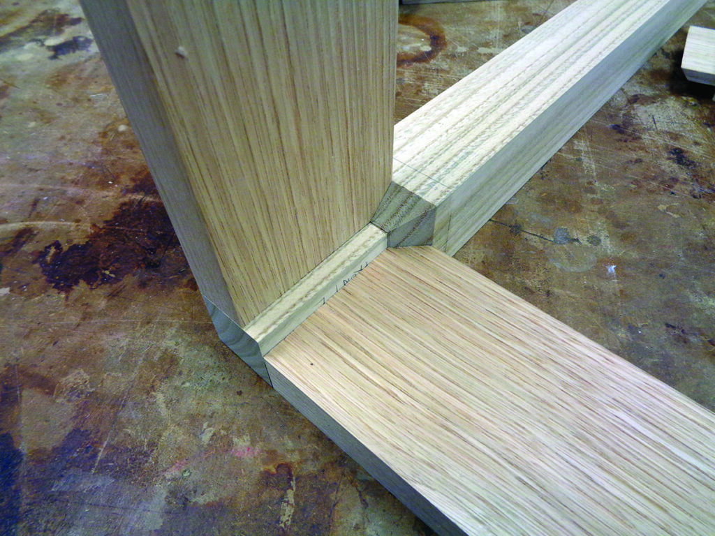
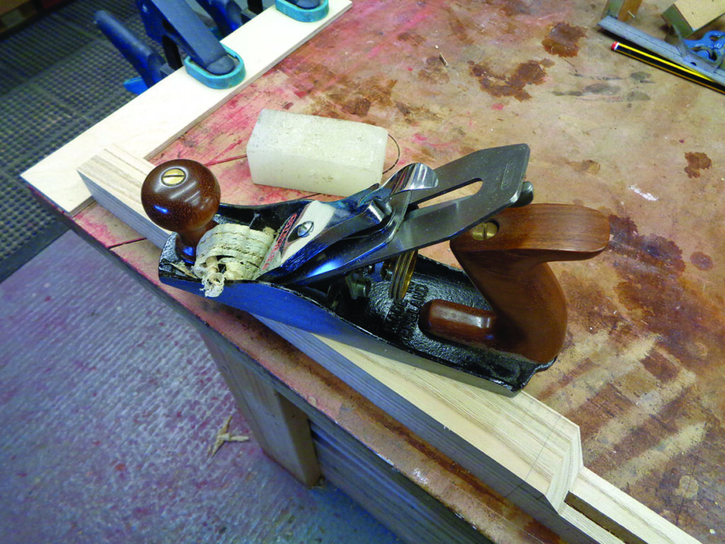
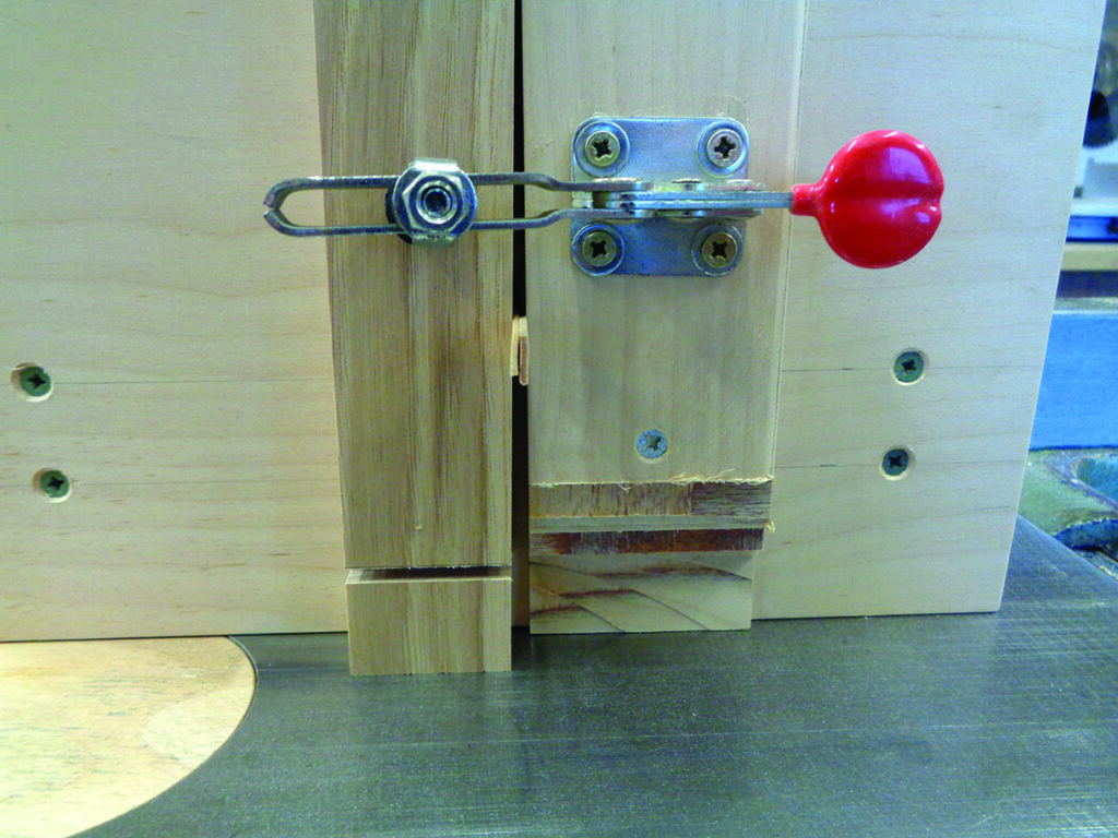
The base of the crockery cabinet was designed to elevate the main body of the cabinet to a comfortable height for accessing delicate crockery items without having to bend too much. Because the cabinet will be heavy when loaded, I decided to include a stretcher rack to add some rigidity to the open frame structure and to provide an additional storage or display option to an otherwise redundant space. After sizing the base timber to 0.5mm over finished dimension, I cleaned up all surfaces except those still to be worked with my Stanley No. 4 to remove machine marks. I then marked out all of the components ready to process the joinery. The next step was to mortise the legs ready to accept the aprons and stretcher rails. I do this while still square as it is easier to grip the timber in the machine vice. On this base frame I decided to mitre the aprons in to the top of the legs so that visually the leg section matched the width of the face frame on the cabinet above. This procedure was carried out on the tablesaw cutting the mitres first before removing the waste with my tenoning jig. The next step was to cut the tapers on the legs. I like to cut tapers on a sacrificial parallel board, lining up the cut line with the edge of the board and quickly pinning some stop blocks to hold the leg in place. I then run this assembly through the saw to remove the waste. Once all the legs have been cut I remove the saw marks with my finely set Stanley No. 4.
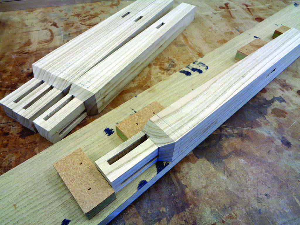
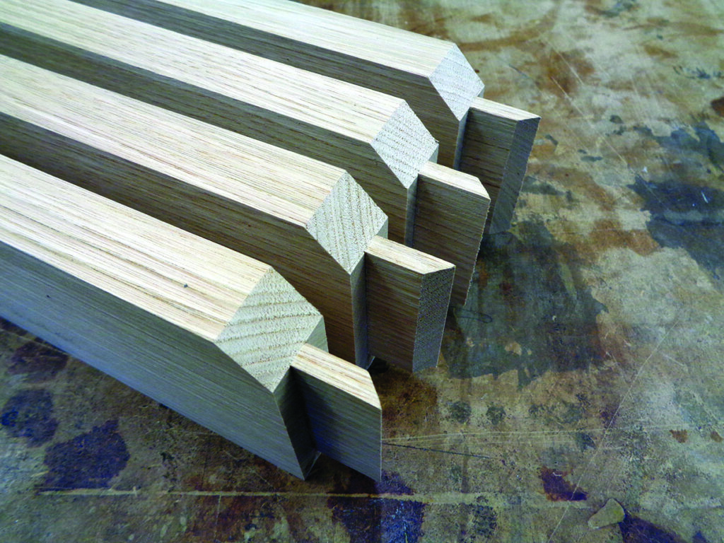
The next procedure is to tenon the aprons and stretcher rails. Once again I do this on the tablesaw, first cutting the shoulders, then removing the waste with my tenoning jig. I mitred the apron tenons on this application because I had reduced the top of the legs for aesthetic reasons and wanted to maintain as much long grain adhesion as possible. Once the tenons were formed on the aprons I tipped the blade over to 45° and clamped a block to the tablesaw fence to register the shoulder line and cut the apron mitres to mate with the legs. The stretcher rails needed to be angled appropriately to meet with the taper on the legs. This was achieved by cutting the angled ends first then using the same technique as with the aprons but using the cut end as the datum face on the fence and the bed of the saw adjusting the angles on the mitre fence and tenoning jig
to remove the waste.
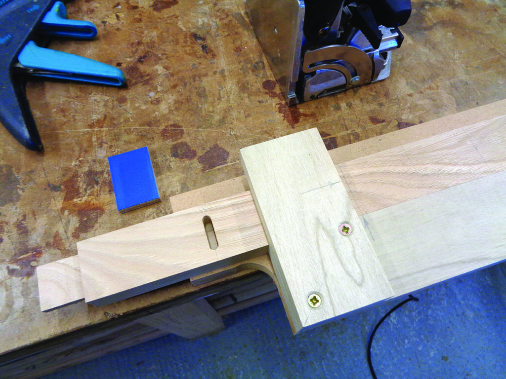
I chose to attach the stretcher rack section to the stretcher rails with Domino biscuits using a simple spacing jig to set the position of the rack elements. This method is easy to mark out, incredibly accurate and because of the precision fit of the Domino biscuit very strong for the task at hand. Before glue up I ran a 3 x 3mm chamfer around the inside show faces of the legs and aprons on the router table ready to match detailing on the cabinet above and added a central rib to the aprons to keep front and back parallel. I also added a spacer rail around the top of the base to form the 7mm shadow gap between the base and cabinet, which doubled as a button rail for fixing to the top carcass. The base was then assembled and glued-up leaving just the sharp edges to be eased and a little light sanding.