Philippa Lobb takes us through the manufacture of a bar stool that champions wood joints and traditional craftsmanship
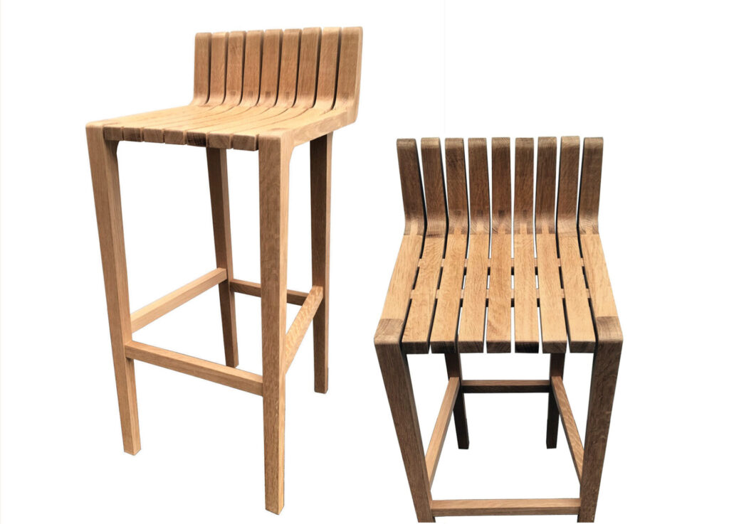
The Akin Stool II is a further development of the original Akin Stool, which was the product of my final project at Northumbria University. This project was an analysis into the design and manufacture of bar stools while looking into their ergonomics and styles. The aim was to create a stool that would fit the needs of the user as well as championing the craftsmanship of hard wood. When given the opportunity to make enhancements on the Akin Stool using user feedback, the Akin Stool II was then produced. It incorporated new features such as the contouring of the seat, adding extra comfort for the user.
To get an understanding of the features and dimensions needed to create a bar stool, I analysed similar products and then prototyped and tested my ideas. I also talked to several interior designers to gain an insight into what the market is looking for.
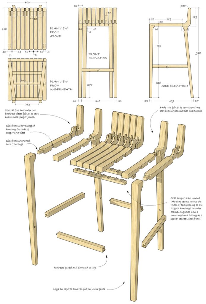
The final stool took inspiration from several designs, including the Hamper sofa by Ezio Riva and Arturo Montanelli, which has a beamed structure. Made from nine solid oak beams, the Akin Stool II is constructed with finger joints that give a comfortable, mid-height backrest, as well as displaying traditional craftsmanship.
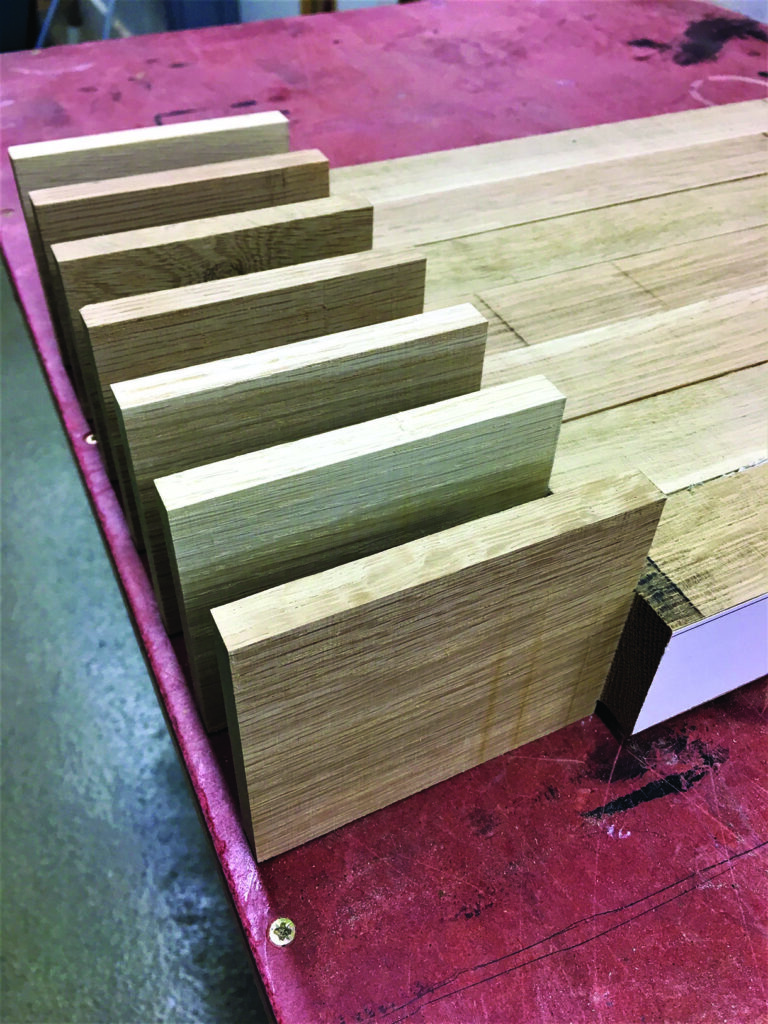
Preparing the finger joints
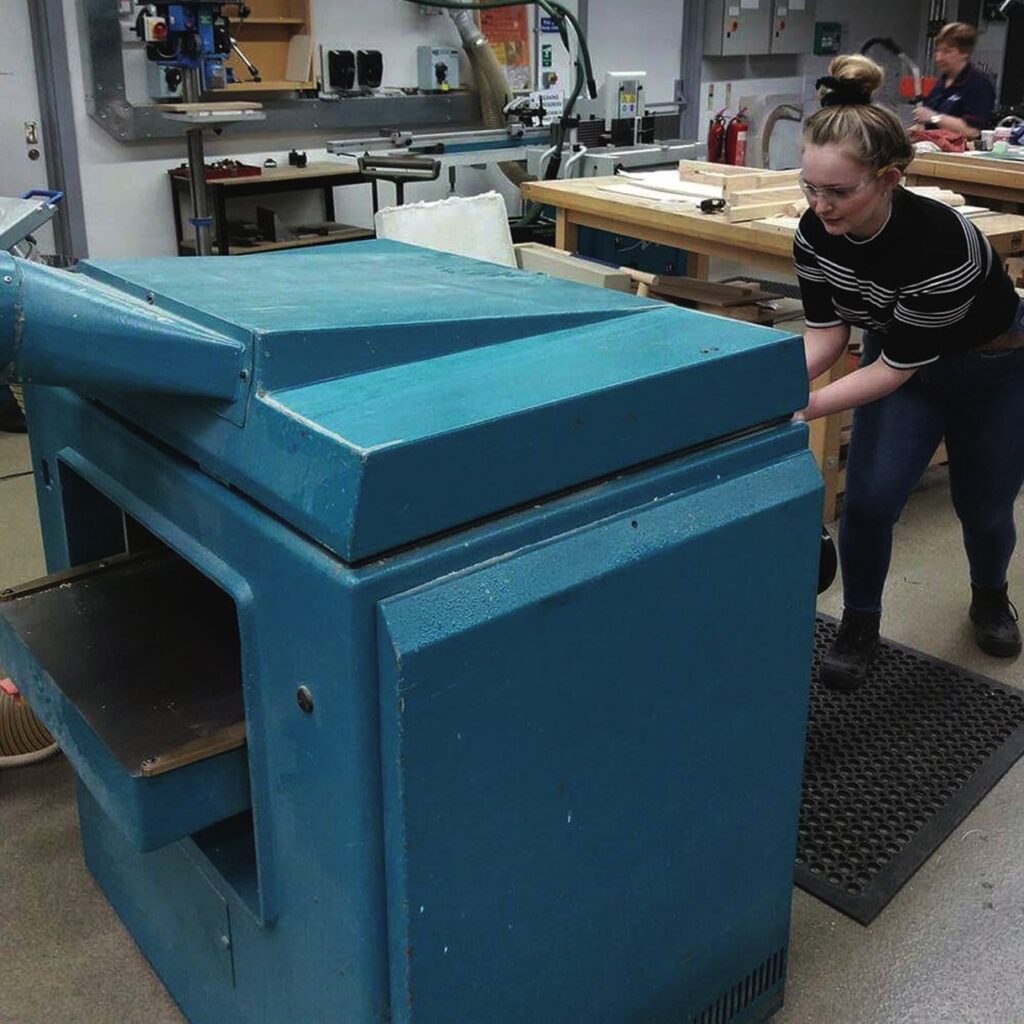
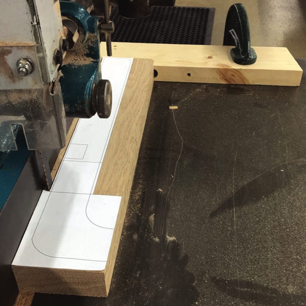
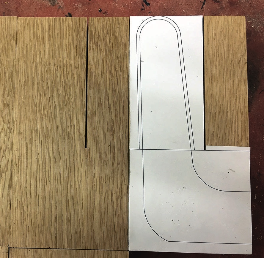
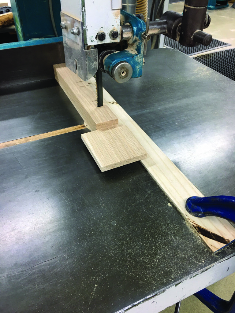
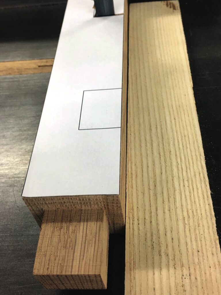
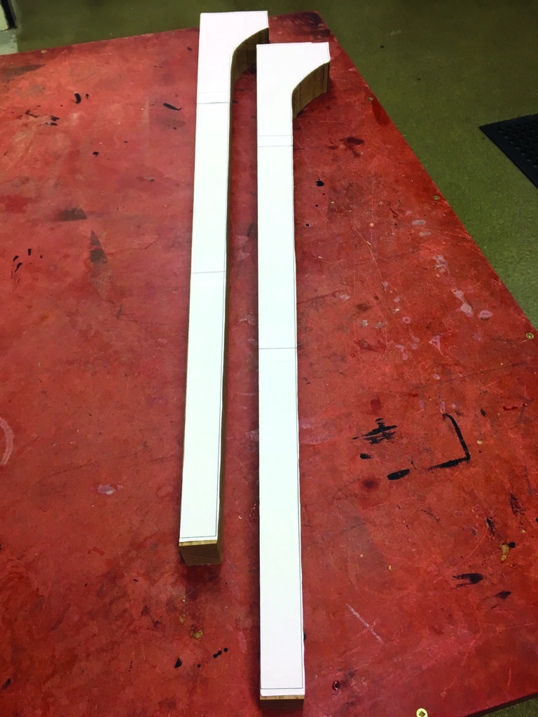
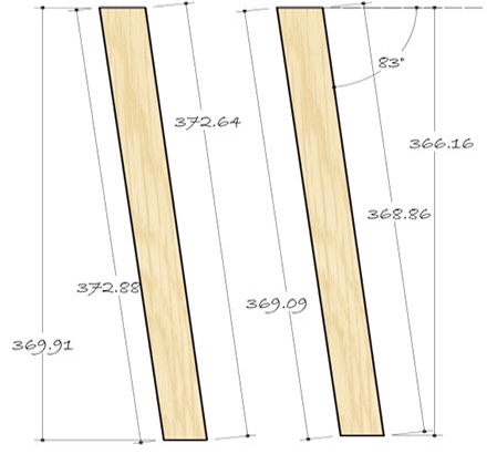
The oak was firstly planed, thicknessed and cut into the seven identical sizes for the seat and the seven identical pieces for the backrest, which would then be joined to create the finger joints. Sticking a printed out 1:1 scale CAD drawing onto one of each of the seven identical pieces gave me a template to follow. The bandsaw guard was set and another jig was set up on the bandsaw table using a straight rectangular piece of wood and a G clamp. Setting up the guard and jig meant that once the first piece of wood was cut using the template the others could be cut to the same size restrictions, making them all uniform.
Cutting the gaps for the lap joints under the beams
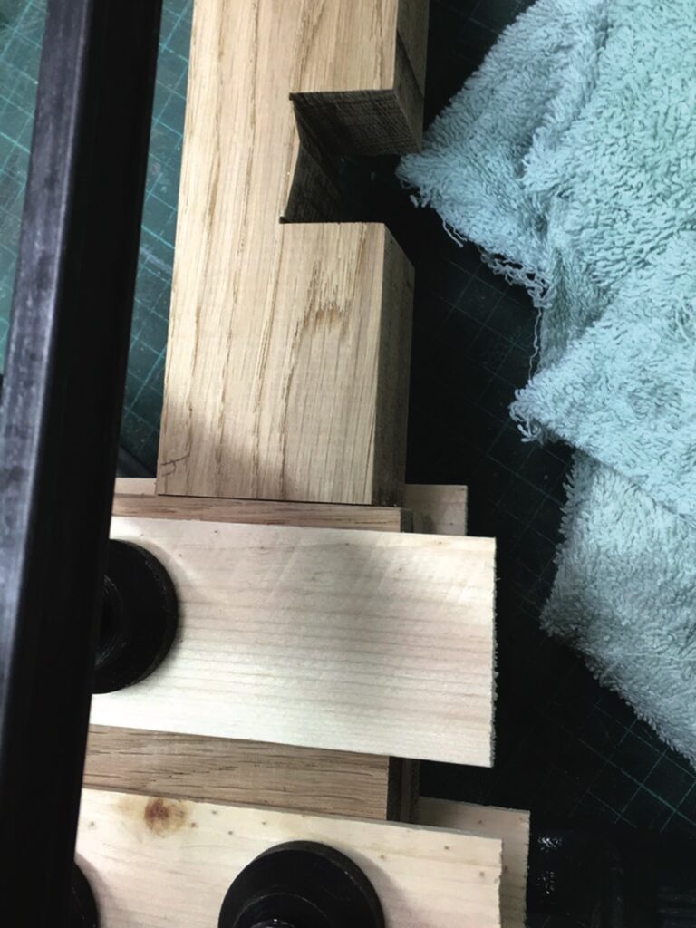
While cutting the finger joints on the bandsaw, the same jig and guards were also used for the lap joints on the base of the beams. The waste material could not all be removed on the bandsaw due to the blade not being able to access it. Therefore, as much as possible was removed by cutting into the waste material at angles between the guidelines cut with precision using the guard and jig. Once this was done, the remaining small triangle was removed using a chisel. A piece of scrap pine was placed as a base under the beam to be chiselled down onto it, this avoided ‘breakout’ of the grain as it was forced down under pressure. This process was also applied to the other two simple rectangular beams that made up the final seat. They attached to the back legs and therefore did not incorporate finger joints, instead there was a tenon on one end which connected to the back leg. The two beams that were at each end of the seat did not have their lap joints cut in this way, as the slats underneath were not visible from the sides. The waste material from these lap joints was instead removed using the mortise drill and then neatened using a chisel.
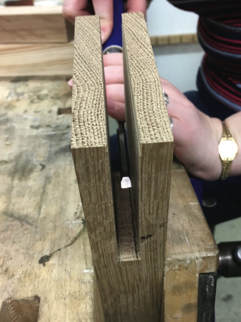
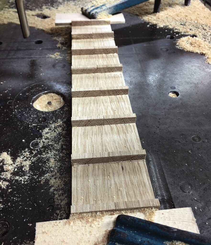
Interlocking and glueing the finger joints
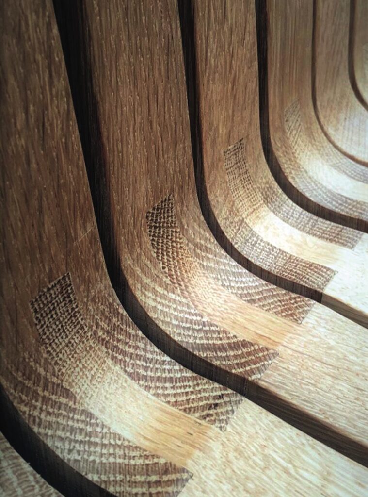
The joints were made up of three fingers of the same width. The seven backrest pieces have the two fingers on the outside with the gap in the middle; this was achieved by cutting the guidelines on the bandsaw and then chiselling the centre piece away to form the gap. The seat pieces have one finger in the centre, which was created by removing the outside pieces on the bandsaw. Making sure these joints fitted together snuggly with no visible gaps required a lot of patience and accuracy. The joints were glued using PVA and left to dry while clamped in vices, extra clamps were used so that pressure was applied equally and evenly.
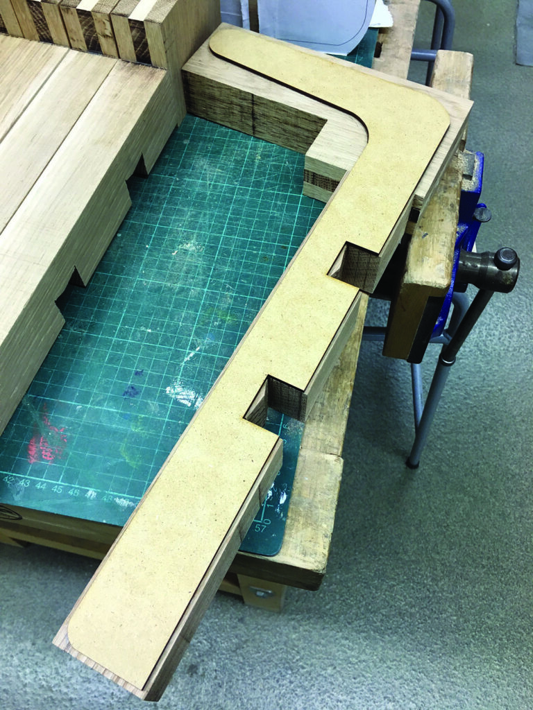
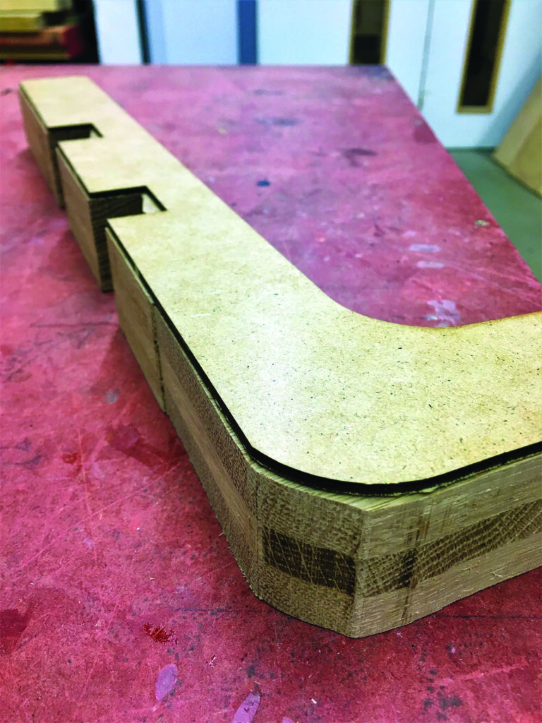
Final shaping of the seat beams
A 1:1 scale side view of the seat beams was laser cut from a sheet of MDF and used as a template. Using double-sided tape, it was stuck to each glued joint and one by one cut around using the bandsaw and then sanded on the bobbin and belt sanders so that each beam was an accurate replica of the template. Cutting each beam separately also gave me the opportunity to add the recessed contours of the seat into each beam, which would give extra comfort to the sitter. The two end beams were separated from the rest during this process. They were shaped in the same way but they do not have a recess cut into them. These two beams also attached to the two front legs and therefore were shorter and had tenons cut into the ends of them to form the joints that would connect them to the front legs.
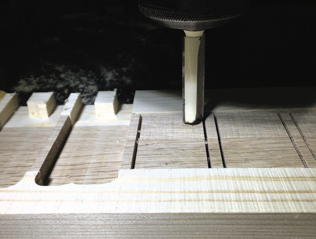
Making the slats and attaching the beams
The nine beams that form the seat are held together by being lap jointed onto two supporting pieces of wood that run horizontally underneath. These pieces of wood also keep the beams evenly separated using manufactured spacers. The over-head router was used to machine the beam width into the supports at identical intervals and the raised sections left were used as spacers to keep the beams uniformly separated. The pieces were clamped between two pieces of pine to avoid break-out, which could have also caused the thinner, more fragile pieces to break away.
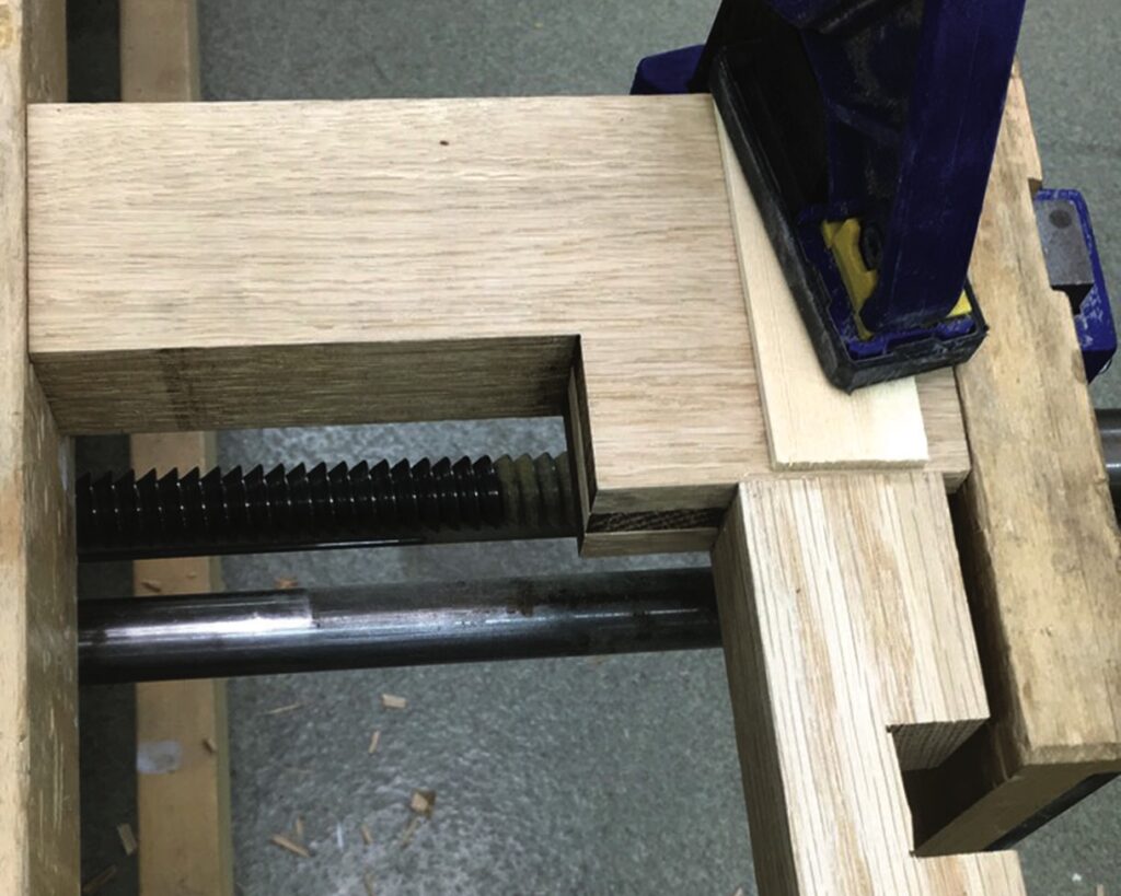
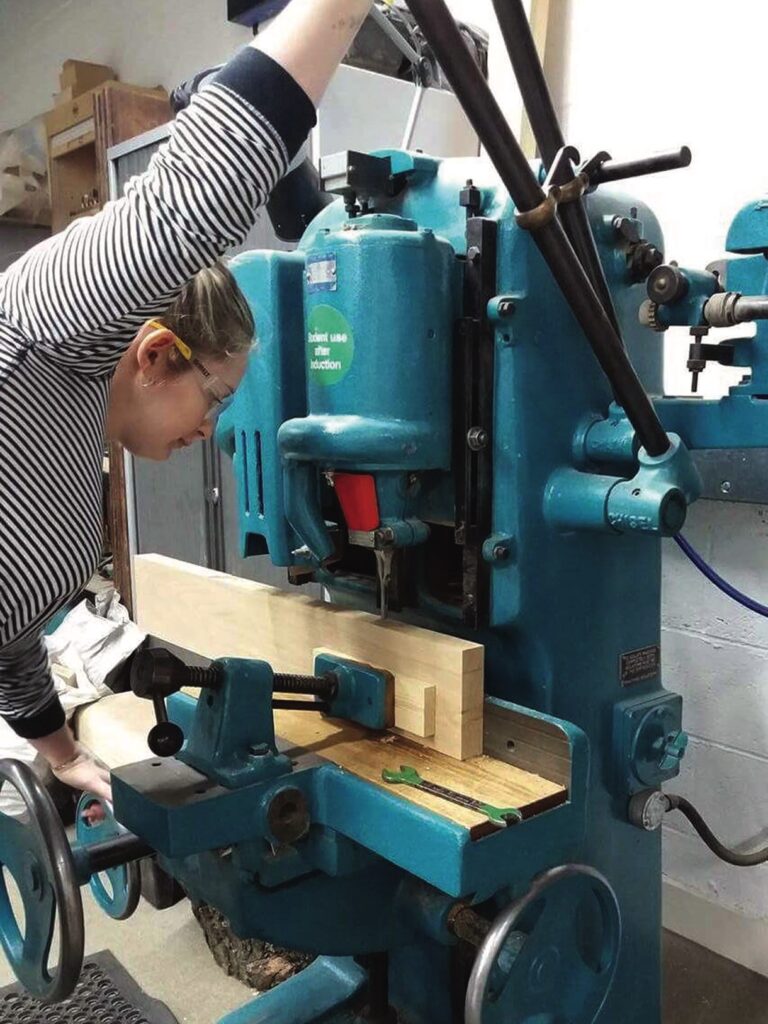
Shaping the legs and connecting the footrests
Before cutting the legs, the mortise was created using the mortise drill. This was done first so that the edge that was being drilled into and the edge that was rested on the drill table were parallel creating a hole drilled at 90°. Therefore, when the tenon was inserted the seat beam joining onto the back leg would be parallel to the floor. The front and back legs were straightforward shapes to produce, as a template was printed and glued onto the wood and then cut around on the bandsaw. To make sure the pairs were the same, double-sided tape was used to temporarily glue them together while they were sanded and shaped.
As for the footrests, the overall length, width and height were easily cut on the tablesaw; the angles, however, were more complicated as the side footrests had compound angles at each end. These compound angles were firstly worked out using CAD drawings. Once a detailed sketch was done, the angles were then created on the disc sander, as the guard on the table could be rotated to form one angle, while the table could also be tilted to form another. Once set to the correct angles, the wood was quickly and easily sanded into shape.
Glueing the stool together
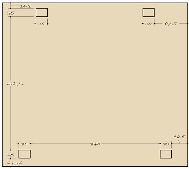
When glueing the final stool together, the fewer pieces to glue at once, the easier the task. Therefore, the process had to be done in stages. Firstly, the five middle beams of the seat were glued and clamped onto the two slats that hold the central seat together. The front legs were attached to the seat beams using Domino joints and liberally glued. It was important to make sure they were the correct beams as the end beams had a different design. The back legs were then glued to their adjoining beams by connecting the mortise and tenon joints. These three sections then had to be joined together while the footrests were in their correct position held in place using 10mm dowel. This was a tricky process that required many pairs of hands. A handy tool used, however, was a floor template, which was measured using the CAD drawings of the base of the stool. The template showed where the feet of the stool should sit and had pieces of scrap pine drilled around these areas to hold the legs in place. This meant that once the stool was put together it would not move
or skew out of place.
Finishing
The stool was left over night to allow the glue to dry and the clamps were removed in the morning. A lot of hand sanding was done before glueing as the pieces, being separate, were easier to handle. However, final sanding was done with finer glass paper to create a smooth finish with no sharp edges. An electric hand sander was used to smooth the gradient on the seat contour especially on the two outside beams as they did not have a contour cut to begin with on the bandsaw. Once the wood was smooth and all imperfections removed, the finish was applied. In this case it was natural beeswax to enhance the oak grain without changing its colour or texture, this worked especially well on the finger joints.
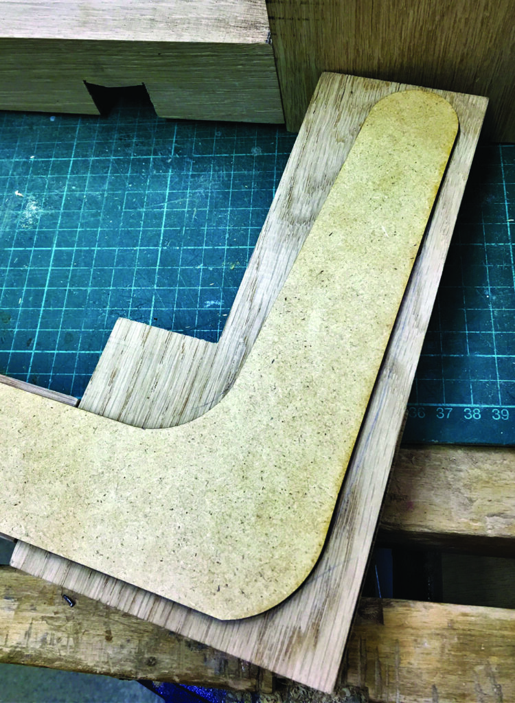
Leaving a rectangle around the finger joint area
A large rectangle was left around the curve of both finger joint pieces for a couple of reasons. Firstly, it was easier to match up a finger joint to straight edges rather than curved ones. Secondly, it gave a larger surface area for clamping once the glue was applied, meaning more pressure could be put on the interlocking pieces to ensure they stayed together and glued firm. Although more waste material was produced, it was worth it to make sure the seven curves were as identical as possible and therefore lined up accurately.
The extra waste made it easier to get identical curves
Plans