Matt Estlea identifies a few ground rules to ensure your layout lines are ones you can trust
Over three separate articles we’re going to look in detail at an exercise project I first saw being used on the Level 1 Furniture Crafts course at Warwickshire College. At first glance it appears quite straightforward and for woodworkers with a few joints under their belt, it will be. But for those new to the craft there’s a lot to be learned in such a small space. During my time studying at Rycotewood Furniture Centre, we occasionally had to make practice frames, small objects or, in one instance, produce various extruded shapes into a scrap piece of poplar using nothing but a chisel. I often found these tasks a bit of a chore as I wanted to get stuck into making something, however I cannot deny that they improved my woodworking dramatically. The great thing about these tasks is that instead of making a project and building multiple skills simultaneously, ultimately leaving your weaknesses trailing behind, you can optimise these practice projects to build on the skills you feel you are lacking.
The frame we are building here will focus entirely on hand tool usage and will emphasise the importance of accurate, clear marking out. When you’re learning, this is usually where things start to go wrong and if some basic techniques aren’t mastered now they’re likely to stay with you for a very long time. At first the eager student will often rush the marking out stage and then wonder why their joints still turn out as gappy and loose as poorly maintained teeth. The answer is simple: they were cutting accurately but to inaccurate lines. In this first article I want to encourage you to take your time, adopt a methodical approach and check for accuracy every time you establish a layout line. After all they contain vital bits of information that will make your joints nice and tight.
Lap joint
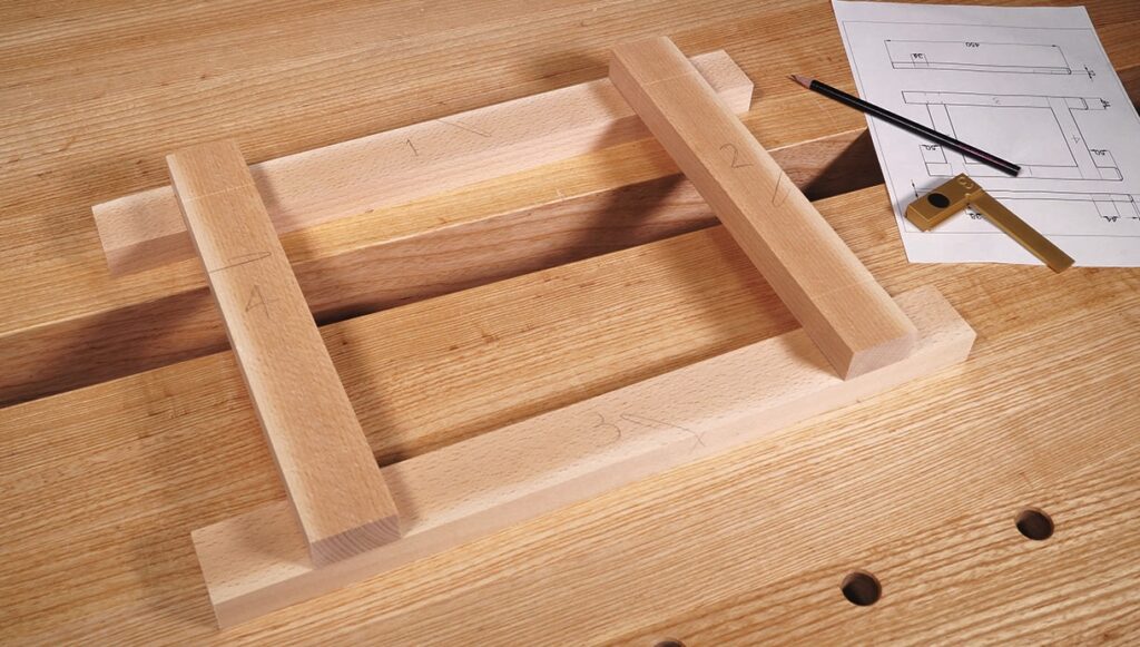
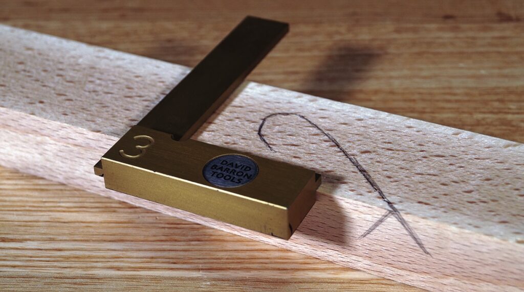
The first thing I did was clearly number the components on the drawing and the corresponding components in front of me, as well as mark the face side and face edge of each component. The traditional way of marking these faces is by drawing the fish-shaped mark (see photo at bottom of page 40) on one face of the component and a V or arrowhead on the adjacent edge where the line terminates. These are extremely important marks as they identify the faces we will be referencing all our marking out from. You can get access to all four sides of the component with a square using these two faces. If you orientate the face edges
to be on the outside of the frame, it guarantees the outside of the frame will be square. If you orientate them on the inside, it guarantees the inside will be square. Choose whichever orientation you like, just don’t mix and match.
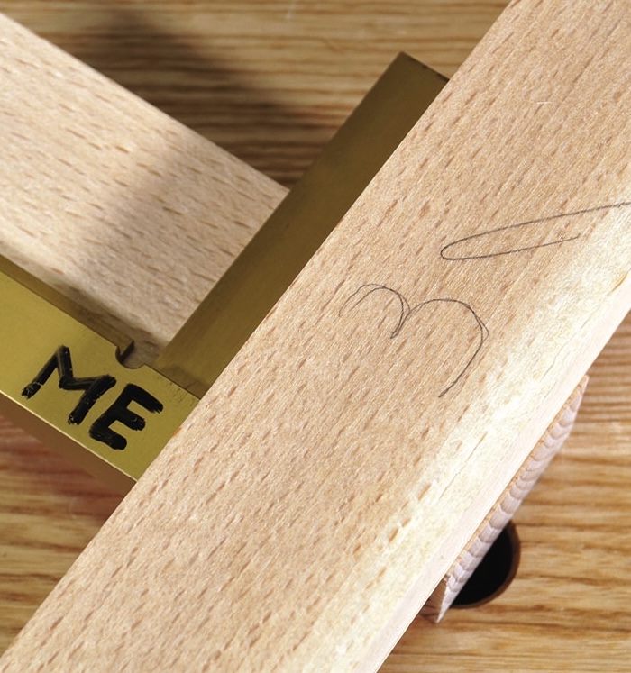
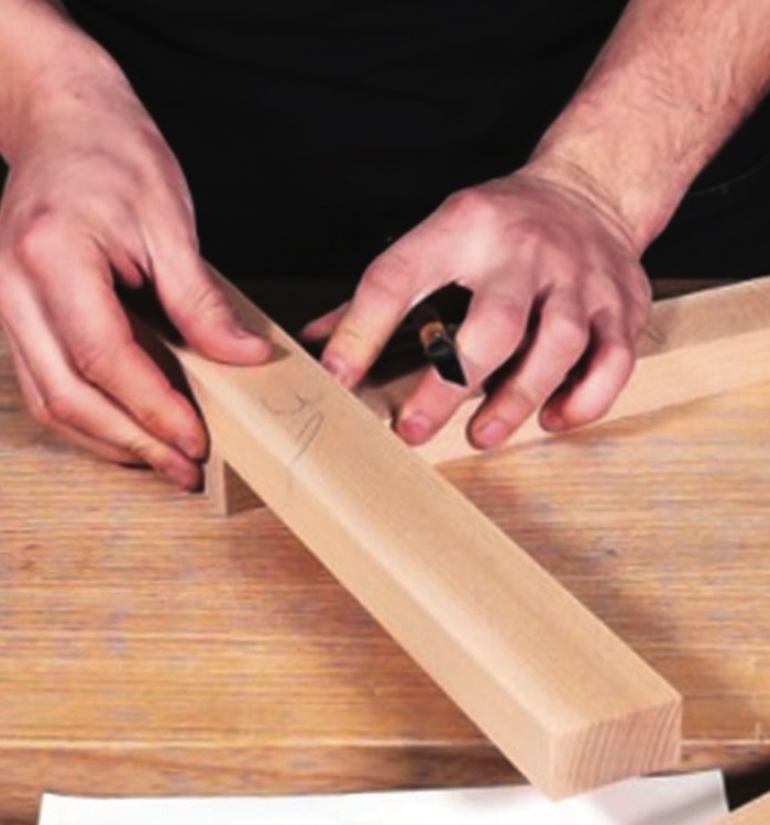
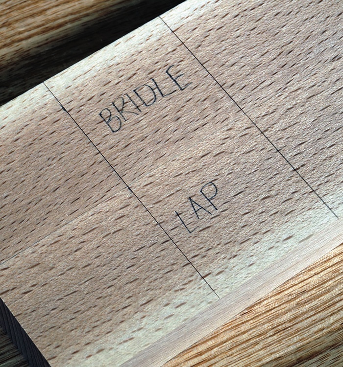
First, we are going to mark out the lap joint and bridle joint simultaneously. To do this I measured in 50mm from the left-hand end of one of the long components and knifed a line across the component using a square referenced from the face edge. Then without moving the square, I put one of the shorter components against it, held it in place and used the component to carefully mark a line on the other side. Thus giving me two knife lines on the long component exactly the same width as the short component. Using the material itself to transfer a critical dimension is far more accurate than relying on a measurement or marking gauge sometimes. If you do the same process on the other long component, you run the risk of your measurements varying slightly and creating a skewed frame. To avoid this, simply flush the end grain up on both components and transfer the knife lines from one component to the other. Now you can square all four of these lines round all four sides of the components. Remember to reference the stock of your square off either the face side or face edge of the component and ensure the knife lines meet perfectly on every corner. Now do exactly the same process on the right-hand side of the frame for the dovetail halving joint and mortise and tenon, but use a very sharp pencil instead of a knife.
Shoulder lines
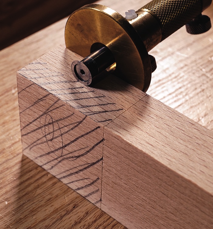
Next we need to scratch the shoulder lines on the shorter components. To do this, reference a square against one of the face edges, butt one of the longer components against the square and slide it up to the end of the shorter component, leaving roughly 0.5mm of end grain overhanging underneath. This means we can plane the joint flush after it is assembled. Remove the longer component and knife across the shorter component using the square. Similar to before, do this on both sides of one component, then accurately transfer it across to the other short component and square the lines around all four sides.
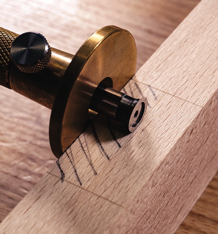
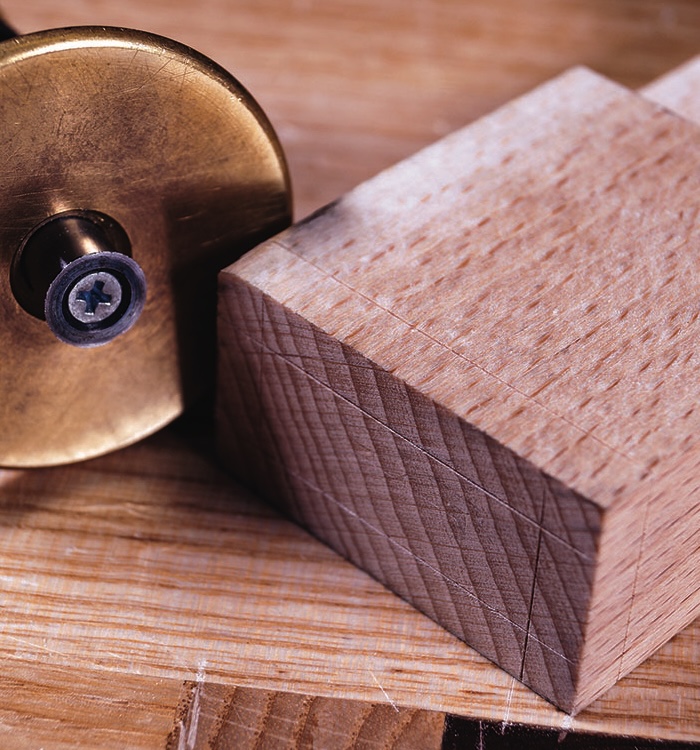
Now we are going to use a marking gauge to scribe the depths of both lap joints. Firstly, set the marking gauge to half the thickness of the stock, in this case 12mm. Scribe a line between the pencil lines on the long component where your dovetail joint is due to be nested and also between the knife lines of the lap joint on the other long component. It’s very important you are referencing the stock of the gauge against the face side at this point. Do this on both edges on both components and do not forget to mark the waste.
We now need to mark the laps on the end of the shorter components. This stage catches a lot of people out because it’s very easy to reference the marking gauge against the waste side of the lap joint, similar to what we did on the long components. However, in doing so, you are not referencing the stock of the gauge against the face side. The reason we are always referencing the stock of the gauge against a face side is because any minor discrepancies when setting the gauge to 12mm will be cancelled out when we assemble the joint. In fact, we could set the gauge to 7mm, for example, and still get a flush joint as a result, providing we are always referencing from the face side of course! Once this is marked out, do not forget to mark the waste material.
Mortise and tenon joint
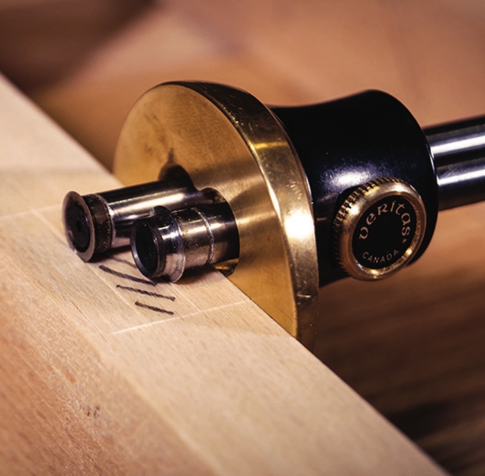
When marking out mortises, you want the walls to be exactly the same width as your mortise chisel. Conveniently, the thickness of these components divided by three is 8mm, so that is the size of the chisel to
use. Now you need to set your mortise gauge heads to be exactly the same width as the 8mm chisel and adjust the offset of the stock to centralise the marking heads on the timber. Scribe between the lines on both sides of the mortise component and around the end grain of the tenon component. I’ll say it again, remember
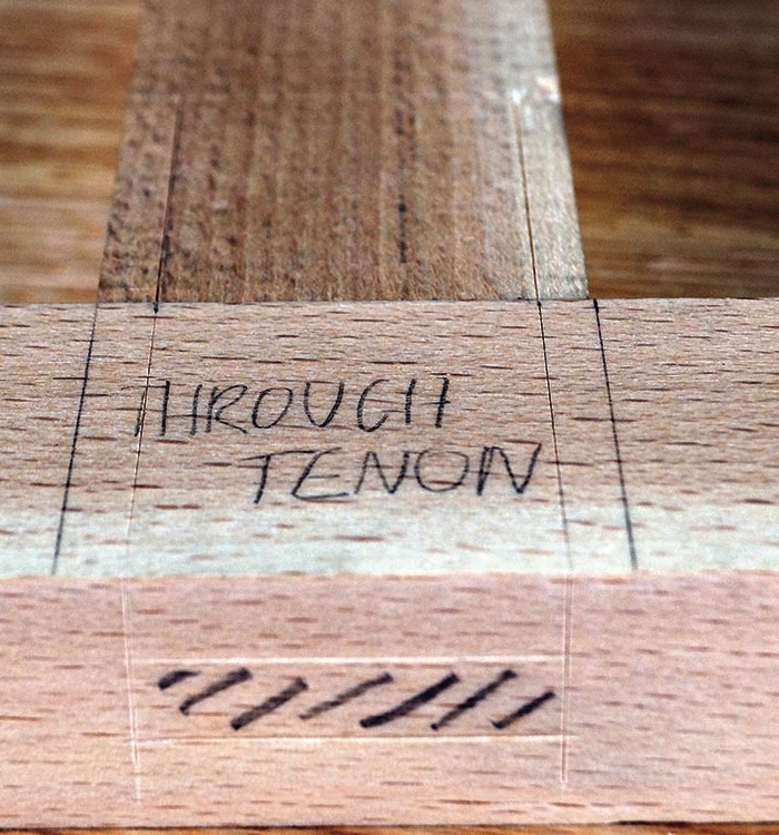
your face sides. To mark the offset of the through tenon from either side measure 5mm in from each side, put a small pencil mark, and use a marking gauge against the face edge of the tenon to score a line from the shoulder line to the end grain. You’ll need to reset your marking gauge to scribe both lines from the same edge, don’t be tempted to use the non-face edge! Once that has been squared, round the end grain and both faces, butt the tenon component against the mortise component, line the corners up with the pencil lines and transfer the marking gauge lines to the mortise component using a knife and square. Scratch those lines down both edges and mark your waste.
Bridle joint
The bridle joint is as simple as using your mortise gauge to scratch around the end grain of the shorter component, and between the knife lines on the longer components. Just be sure to mark your waste as always. The final bit of marking out we need to do is for the small chamfers on the left-hand side of the frame. Again, nice and simple. Set the marking gauge to 6mm, score around all four edges on the cross grain and long grain. That’s it, your marking out is complete.
Warwickshire College
We would like to acknowledge the Furniture Crafts course at Warwickshire College and course leader Jamie Ward for allowing us to recreate this exercise frame