James Bowyer unlocks the methods behind the stack laminated, coopered and shaped backrest on the Cartwright Chair and reveals his techniques to recreate the chair’s characteristic carved dimpled texture
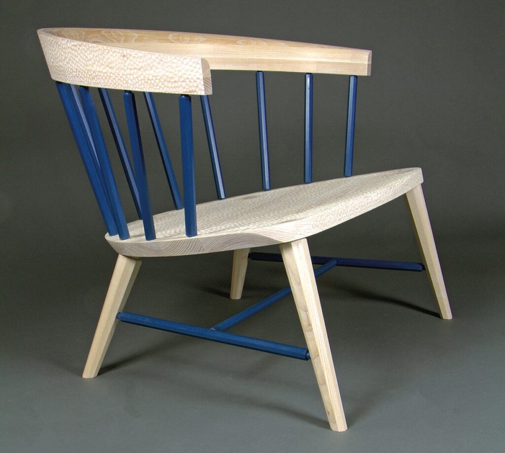
In a candid moment I’d admit that the prospect of designing my first chair filled me with as much dread as it did excitement. When approaching this task, being a speculative piece with no client brief to set parameters, I couldn’t help but recall the words of one of my tutors (an esteemed contributor to this publication), that ‘there’s nothing truly original’. His inference being: don’t try to reinvent the wheel, or in this case the chair. For my inspiration I chose to look back in time, at the rich vernacular history of English chair making and that most iconic of English chairs, the Windsor. My chair would be a contemporary take on this classic style. Drawing as much inspiration from the early Georgian iterations as their 20th-century Scandinavian cousins, I wanted my Windsor to make a valid contribution to the brilliant lexicon of contemporary Windsors. To that end the Cartwright is a generously proportioned, low slung lounge chair. For the purposes of this article I am going to focus my attention on two of the chair’s defining features and most technically interesting and demanding parts: the backrest and the carved dimpled texture on the seat and backrest.
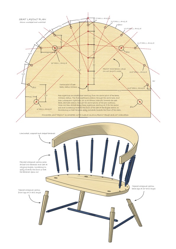
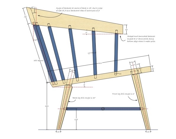
Seat layout and plan
The backrest: design and timber selection
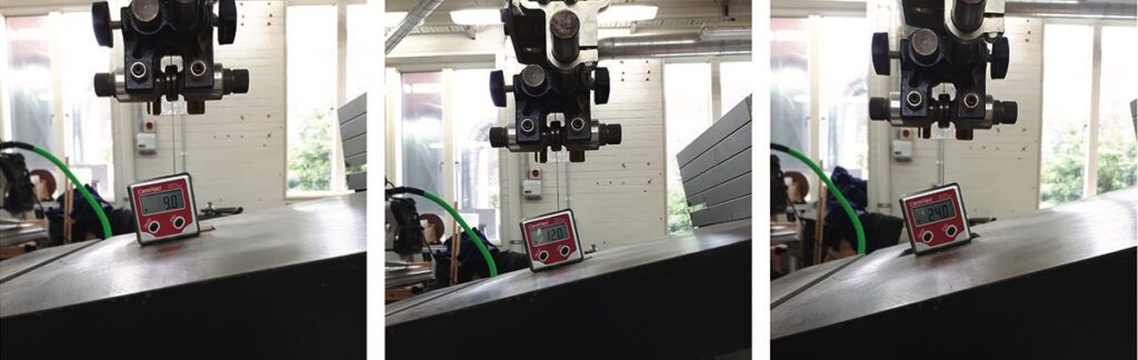
The design of the chair’s backrest is fairly complex. In essence it is a semicircular arch, however, the angle of rake/splay is constantly changing along the curve. Starting with a 9° splay at either end, it becomes a 24°
rake in the middle of the backrest. The whole of the backrest then sits forward on the poles at a 6° negative incline. As such it would have been impossible to steam bend without incurring massive wastage and cutting through too many glue lines in the shaping process.
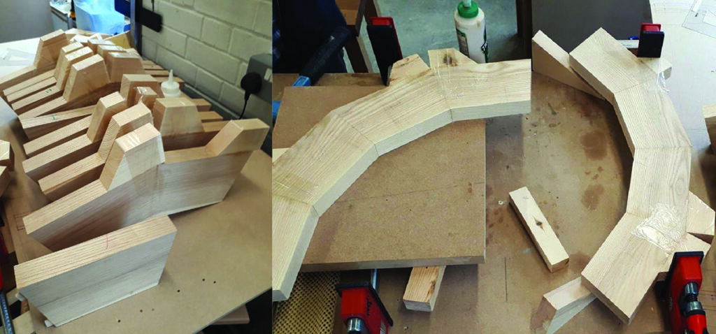
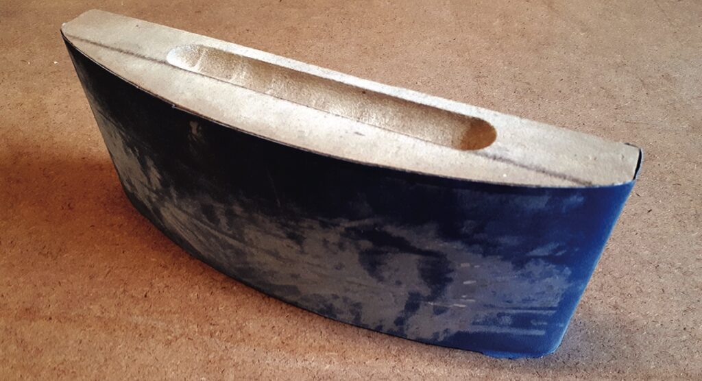
The solution was a stack-laminated structure of three layers, each layer made from coopered trapezoidal sections. The stack lamination is then shaped to form the curved arcing finished backrest. The design gives massive strength and a neater more deliberate arrangement of glue lines (more on that later).
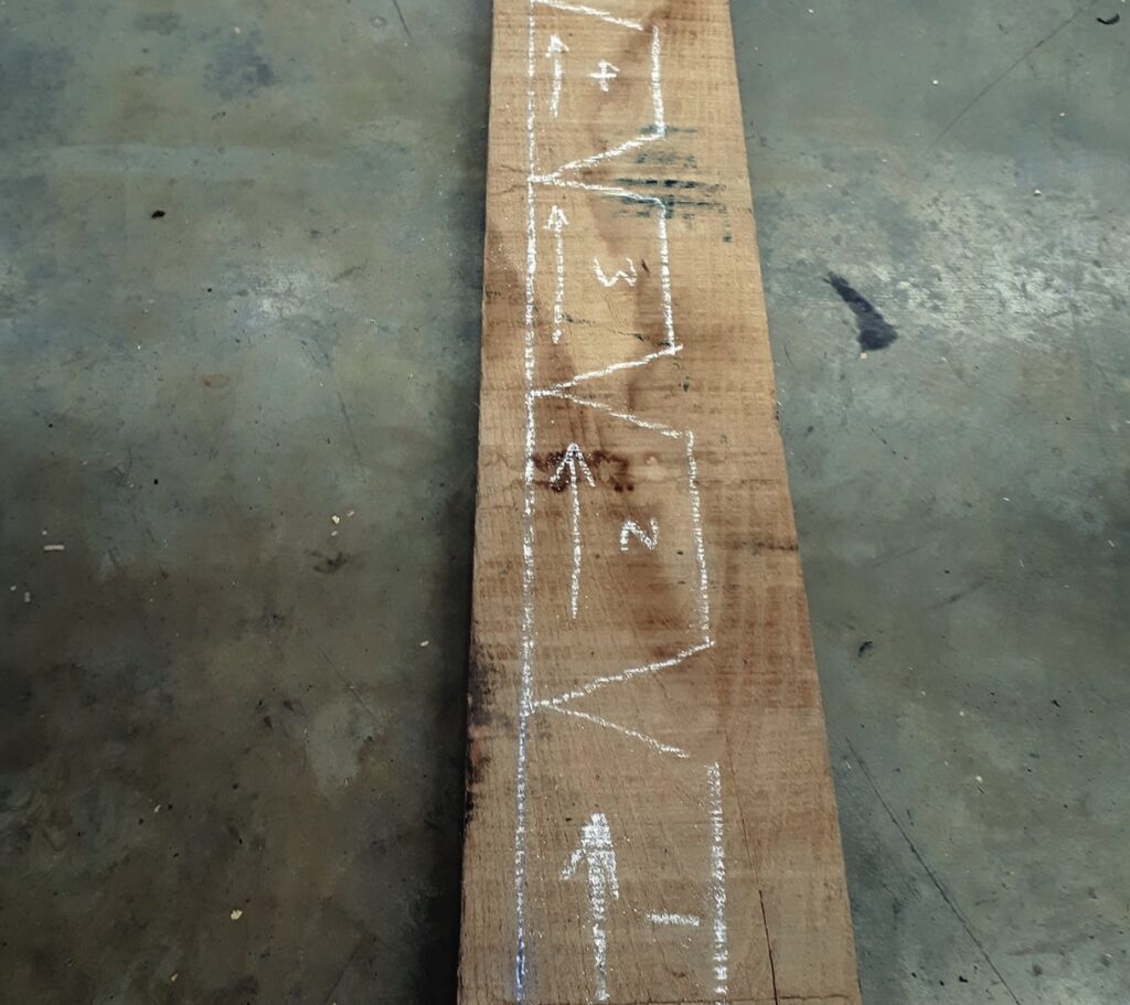
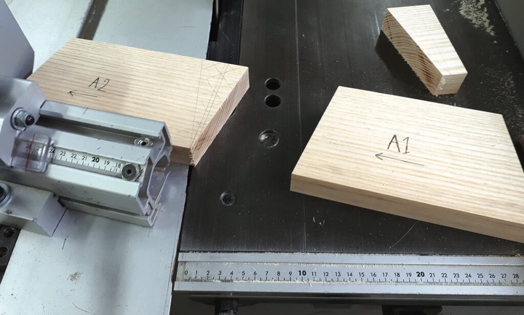
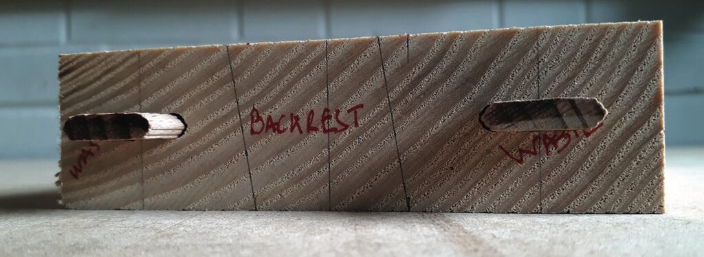
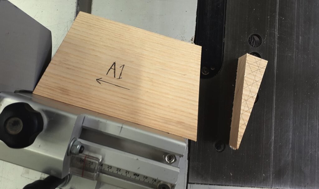
The top layer is made up of nine trapezoidal sections. The middle 10, and the bottom layer another nine, making 28 identical trapezoidal sections in all. First though, careful timber selection is required. Each layer of the lamination requires continuous grain matching around the outside and inside of the curves. The sections need to be cut very carefully so as to remove as little waste as possible between sections, just the width of a saw kerf. Boards were carefully selected ensuring that no blemishes or defects would interrupt the continuous flow of the grain.
Each trapezoidal section was coded with a letter and number as it came off the saw, denoting the layer and its place in the sequence, to enable quick re-arrangement at the bench.
Assembling the coopered layers and sacrificial Dominoes
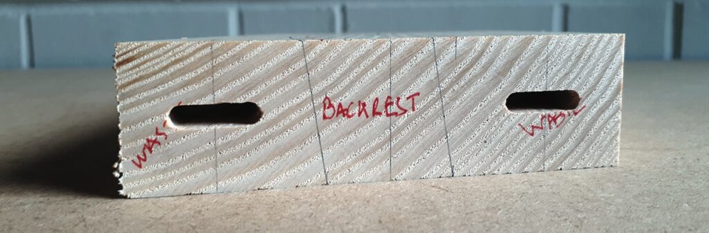
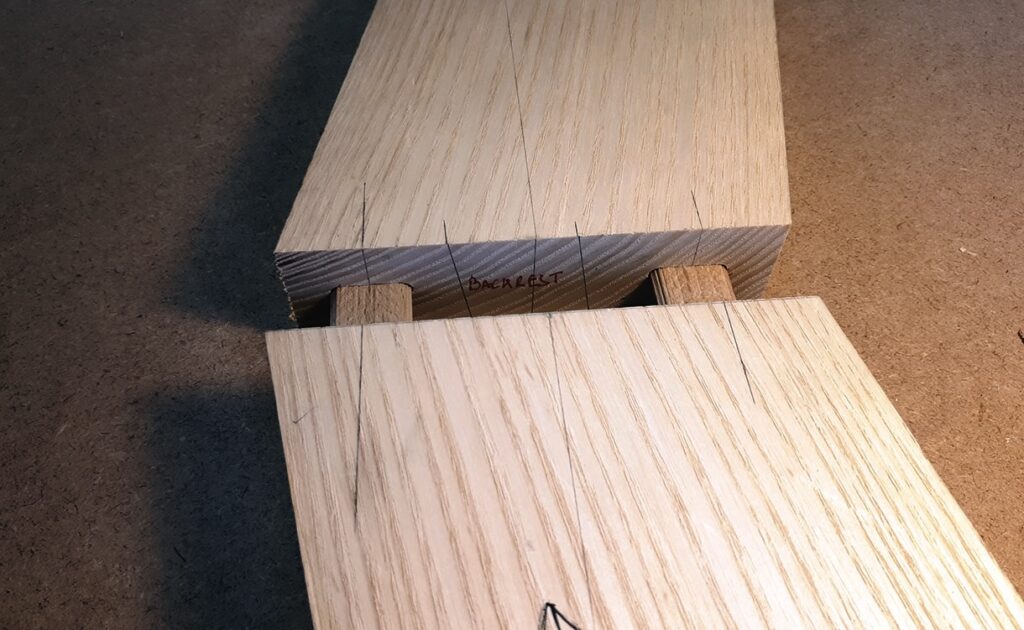
Once cut and arranged at the bench, each section has two Dominoes cut in to the end grain. While these Dominoes are ultimately sacrificial, removed with the waste in shaping, they provide essential alignment and prevent slippage when glueing. The Dominoes are placed at the inner and outer extremities of the trapezium’s width, aligned 20mm in from each edge. This leaves the middle area, what will ultimately become the backrest once shaped, clear of Dominoes, ensuring there is no chance of hitting and exposing a Domino when shaping.
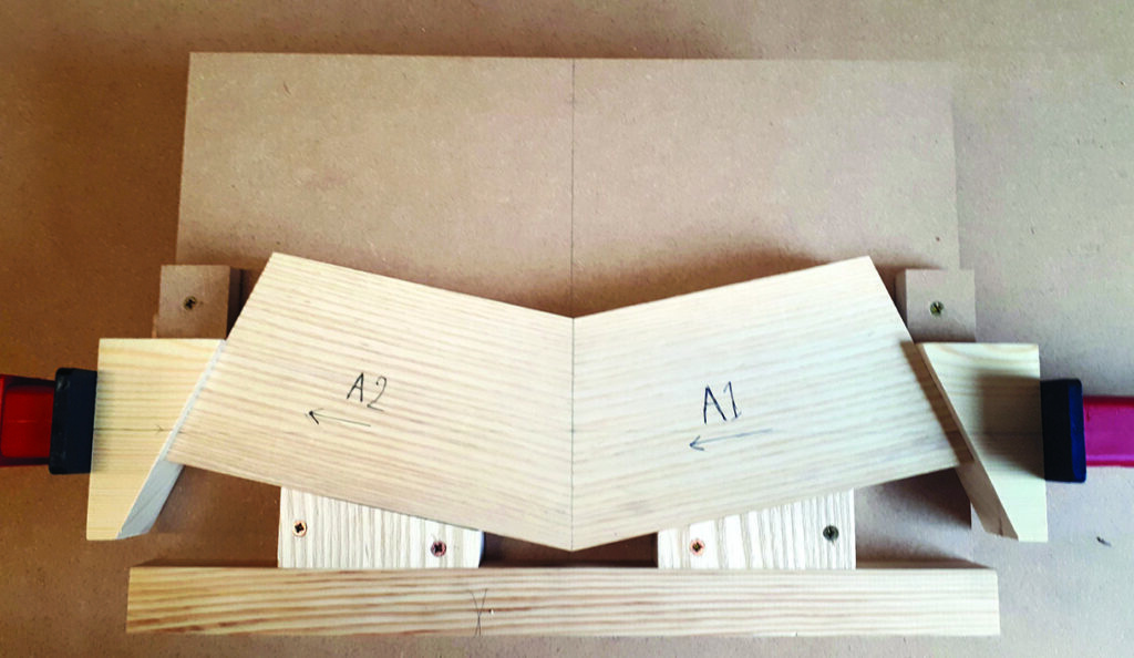
Each layer of the stack lamination would be glued up in three stages. Firstly, in pairs, then two pairs together and finally altogether as a complete layer. The sections were arranged into pairs and glued together end grain to end grain. Achieving perfect glue lines across all the joints is absolutely vital to the success of a stack lamination, therefore I made a jig that at first glance might look like overkill, but when repeating this process 19 times, proved invaluable. The jig was very simple, consisting of a 25mm MDF board, with a 35 x 35mm softwood stop at the back. Offcuts from the trapezoids are then positioned and screwed down so as to hold the two sections in place at the correct angle. Softwood wedges, calculated to give parallel pressure across the centre of the joint are then used at either end with a single Bessey K Revo clamp applying ample pressure. The next step was to glue each adjacent set of pairs together. In order to glue these together, additional angled blocks were glued on to the outside of the trapezoidal sections. These blocks, also sacrificial, enabled easy clamping by providing parallel surfaces that intersected the middle of the joint, again ensuring a clean glue line in the area of the joint that would ultimately be left after shaping. The same process was then repeated to complete the glue-up of each layer.
Glueing the laminations
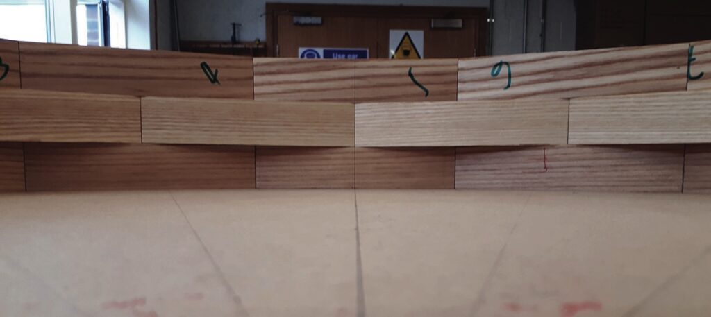
Once assembled, each coopered layer of the stack lamination is passed over the surface planer to ensure a clean and flat glueing surface. The middle layer requires flattening on both top and bottom surfaces. Satisfied with the result off the surface planer, I then closely check flatness with a straightedge and fettle where necessary with a jack plane to ensure I have four absolutely flat, clean glueing surfaces. Due to the stack laminated, coopered structure the effect is brick-like, and just as any bricklayer looks for neat alignment, I was very particular in lining up the joints in the top and bottom layers of the stack. This accuracy of alignment becomes highly visible once shaped and sanded.
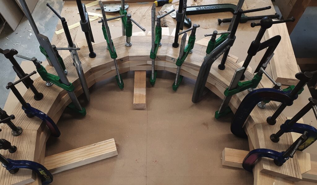
The clamping process is slow and careful, using regular PVA glue to leave the faintest glue lines possible. F and G clamps suffice, ensuring pressure is focused in the central area of the coopered layers, which is left behind once shaped. Clamping blocks are not required, as both top and bottom surfaces will be planed and shaped, with a considerable amount of material coming off.
Marking the curves
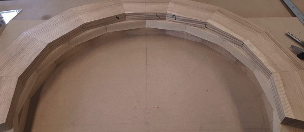
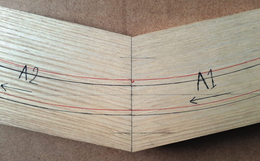
Using a trammel and my 1:1 scale rod, I transferred the curves on to the top and bottom faces ensuring that both curves were shown on the upward face. During shaping those lines would be all I have to work to, so needed to be highly visible. The red line denotes the position of the curve on the underside, front and back. And the black line shows the line of the curve on the top of the backrest, front and back.
Roughing the shape
As the angle of splay at both ends of the back rest is 9°, going up to 24° at the centre point, the first cut I made was at 9° all the way round the curve. For the inside of the curve I followed the innermost red line, denoting the position of the curve on the bottom of the backrest. When cutting the outside of the curve I followed the outermost black line, denoting the position of the curve on the top of the backrest. I then repeated this process at approximately 12°, for the middle section of the curve, and again a 24° just around the centre of the backrest.
Due to the constantly changing angles of rake and splay around the curve of the backrest, it was impossible to get any machine tooling to carry out the task.
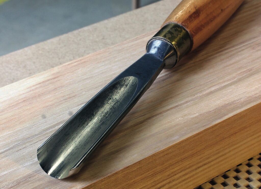
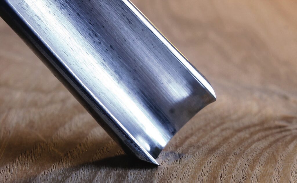
Choosing a carving chisel
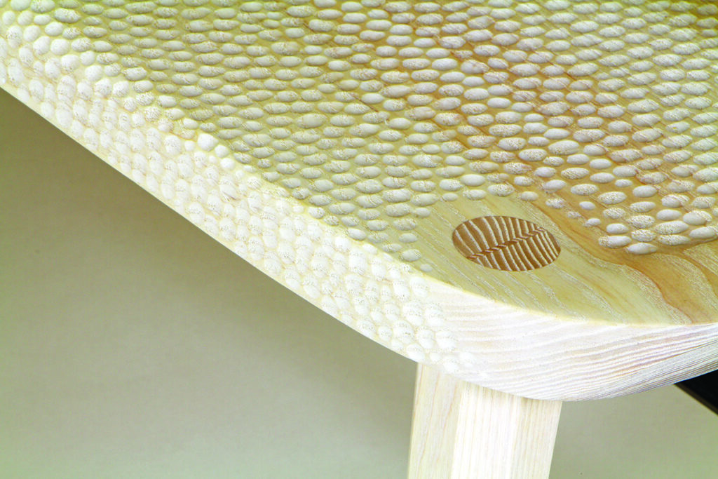
With nearly 4000 hand-carved dimples decorating the seat and backrest of the Cartwright Chair, choosing the correct chisel was fairly crucial. Having tried a variety of Stubai, Pfeil, Marples and Sorby Chisels I eventually opted for the following: 19mm Ashley Isles Straight Gouge (Sweep 10) chisel. For this type of dimple carving, the robust 3mm blade gave the chisel a really solid reliable feel, which gave me confidence in my ability to repeat the cuts and maintain a consistency of cut. The wide, tight curve suited the size of dimple I was looking to carve, around 8mm across and 1–2mm deep, while the slightly meatier handle and short blade made it extremely comfortable for the full duration of the two days’ carving.
Final shaping
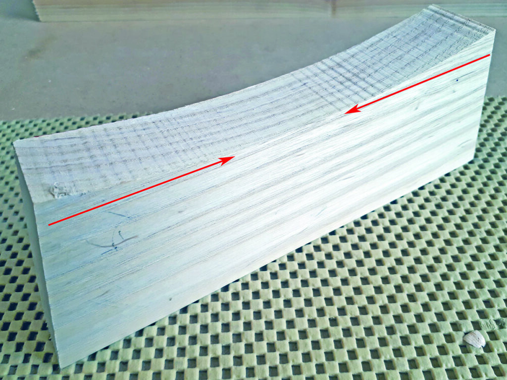
At this stage, the process begins to veer away from jigs, digital bevels and machinery. The remaining shaping process is reliant on instinct, care and my 1:1 rod; while removing material the backrest would constantly be returned to the rod and checked to see where material needed to be removed. The difficulty in making curves out of stack laminated solid sections is that as you cut a curve out of each trapezoidal section the grain direction reverses from one end to the next, and that occurs with every one of the 28 trapezoidal sections in the curve. This means that no blade can take a clean cut, without tearing out somewhere – no matter how well honed. I tried low angle jack planes, low angle block planes, compass planes, round bottomed spokeshaves, flat bottomed spokeshaves, drawknives and scrapers … the result was always the same. Tear-out. Only abrasives would do the job.
Now with a roughed out, faceted curve off the bandsaw the next task was to even out the curve starting on the outside. Initially on the belt sander and with a portable belt sander, then moving to a orbital with a hard pad, I carefully removed the excess material and worked through the grits to fine smooth finish around the curve. Smoothing the inside of the backrest was considerably harder as I couldn’t get the belt sanders on to the curve. As such, most of the waste material needed to be removed with an angle grinder, leaving a relatively uneven surface. With the constantly reversing gain ruling out any blades, I continued the flattening/smoothing process with abrasives. Cabinet scrapers and random orbital sanders follow the gentle undulations left by the angle grinder, but do not remove them. The solution was to make a custom MDF sanding block. I matched the curve of the block to the backrest’s inside curve to increase the surface area in contact with the abrasive. This also helped to maintain the consistent curve and shape when knocking off the little high spots. Once satisfied that I had a smooth even surface, I worked up through the grits to 240 before finishing with a white tinted Osmo 501 hardwax oil, and finally a coat of Osmo 3044 raw, de-nibbing between coats with a non-abrasive pad.
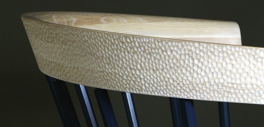
Carving the chair’s dimpled texture
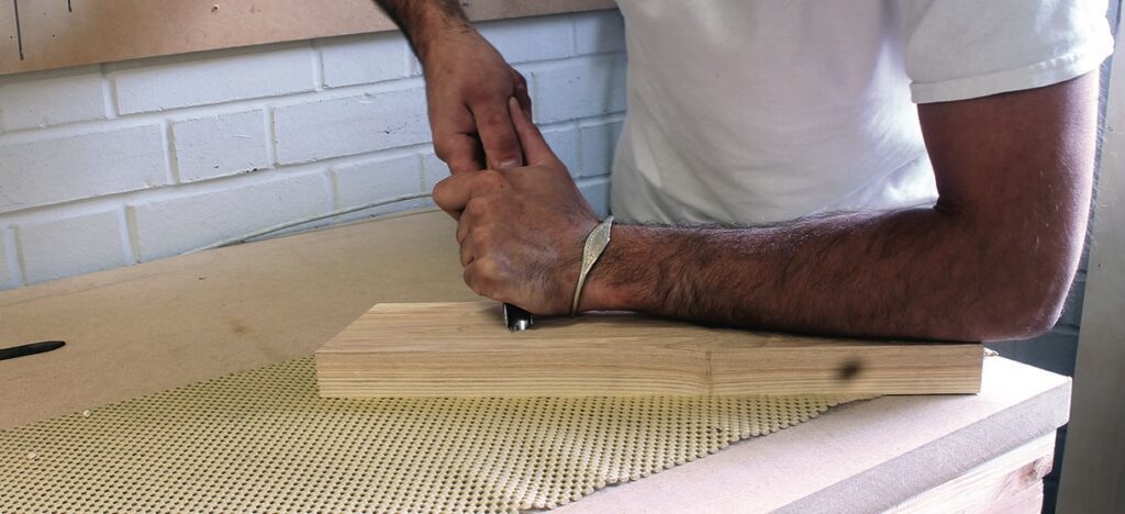
The other of the chair’s most prominent features is the hand-carved, dimpled texture over the seat and back. I incorporated this feature to make oblique references to the historical method of carving Windsor chair seats. Prior to the advent of abrasives, the craftsman’s adze which was used to shape the seat would leave subtly textured carving marks. My dimpled surface texture referenced this rather charming historical idiosyncrasy. In order to achieve this effect, and to maintain the bespoke handcrafted feel this would have to be done by hand. Being right handed, I held the chisel in my right hand, thumb pointed down the shaft. My dominant (right) hand would make the cut, pushing forward, but simultaneously my left would act as a brake. Laid over the top of the chisel and my right hand, my left pushes back against the right controlling the power applied to the cut and offering control and preventing you slipping out of the cut and gouging a great chunk out of your work.
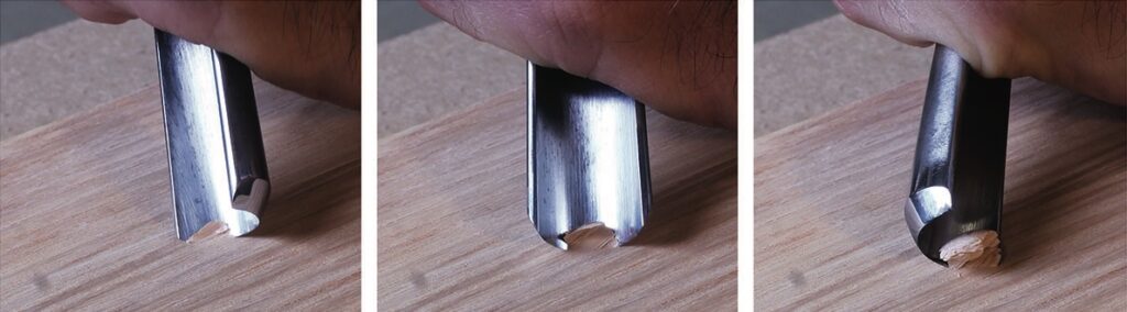
Then in making the cut, I use a rotating motion. Rotating about 45° through each gouging cut – using this rotary action utilises the length of the blade, slicing through the cut rather than forcing it straight. This not only leaves a better finish but is considerably more energy efficient – which when making this number of tiny cuts is fairly crucial.
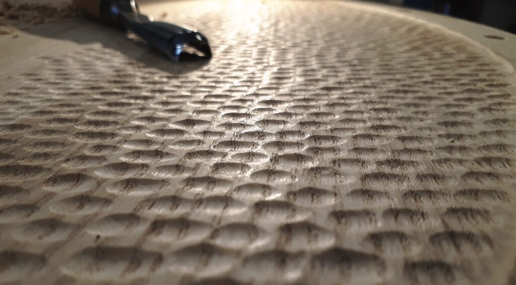
The angle of each cut is also vital. Approaching the start of each cut so that the bevel on the back burnishes the cut as you make it, leaves a perfectly smooth finish in each cut. I worked directly across the grain, to avoid breakout and chipping, and was very careful not to be too greedy in each cut. Making two or three cuts for each dimple if necessary; getting greedy and cutting too deep at first will almost certainly lead to tearing and an unsatisfactory finish. I kept the chisel razor-sharp by keeping a strop to hand and polishing every few minutes, returning to the sharpening stones only when necessary. I also used a small manoeuvrable spotlight at a very low angle to clearly show the size of each dimple, the low angle light producing clear shadows and making it far easier to keep the size of each dimple roughly consistent.
Inspiration
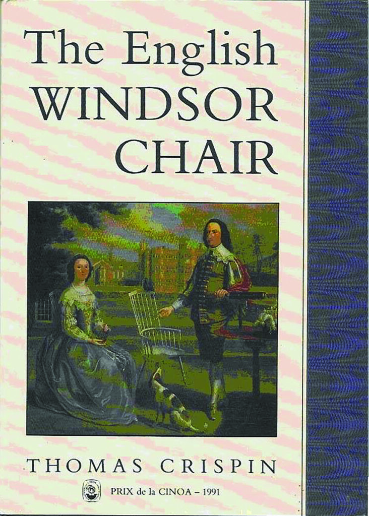
While designing the Cartwright, Thomas Crispin’s excellent historical overview of Windsor chair making in the UK, The English Windsor Chair, revealed some charming idiosyncrasies of early Windsor chair-making techniques, two of which gave rise to the Cartwright’s most distinctive features.
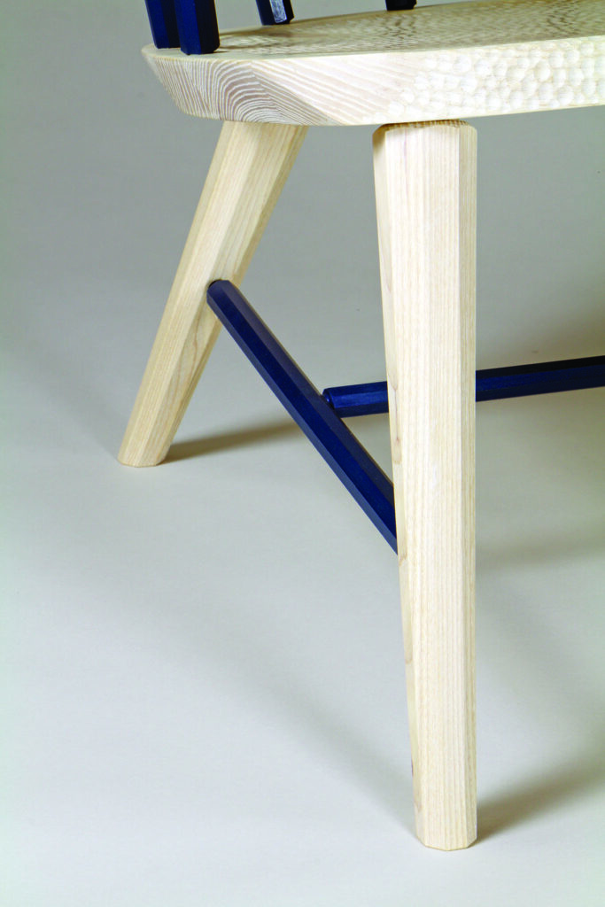
Crispin notes that prior to the advent of abrasives the round-sectioned components – the legs, poles and stretchers – were often made using drawknives and that those drawknives, even in the hands of the most skilled craftsmen would leave tiny facets on the finished components. I was particularly taken with this quirk of production and chose to exaggerate these facets into larger faceted octagonal sectioned legs, poles and stretchers.
Similarly the early 18th-century craftsman’s adze, which was used to hollow out and shape the archetypal ‘Windsor’ seats, would leave the faintest of carving marks in the finished chair. The Cartwright’s hand-carved dimpled texture on the seat and along the outer edge of the backrest sought to make oblique reference to this.