Oak Coffee Table
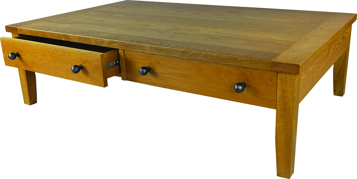
Louise Biggs restores a beautiful oak coffee table
Louise Biggs restores a beautiful oak coffee table
This coffee table is one piece of a suite of furniture made from North American white oak (quercus alba). The clients wanted two large drawers, which they could easily reach the back of. With a dovetailed box forming the drawer carcass, this article will endeavour to show two different ways to cut the dovetails
and how to fit the drawer runners.
What you will need
Table saw
Planer/thicknesser
Mortiser – or mortise chisel by hand
Router table and router
Straight cutter
Dovetail cutter
Tenon saw
Screwdriver
Drill press – or hand drill
Drill bits and countersink
Sash and ‘G’ cramps
Squares – various sizes
Chisels – various sizes
Planes – various sizes
Dovetail/gents saw
Sliding bevel
Mallet or a dovetail jig
PPE – eye and breathing protection, plus gloves
Main construction
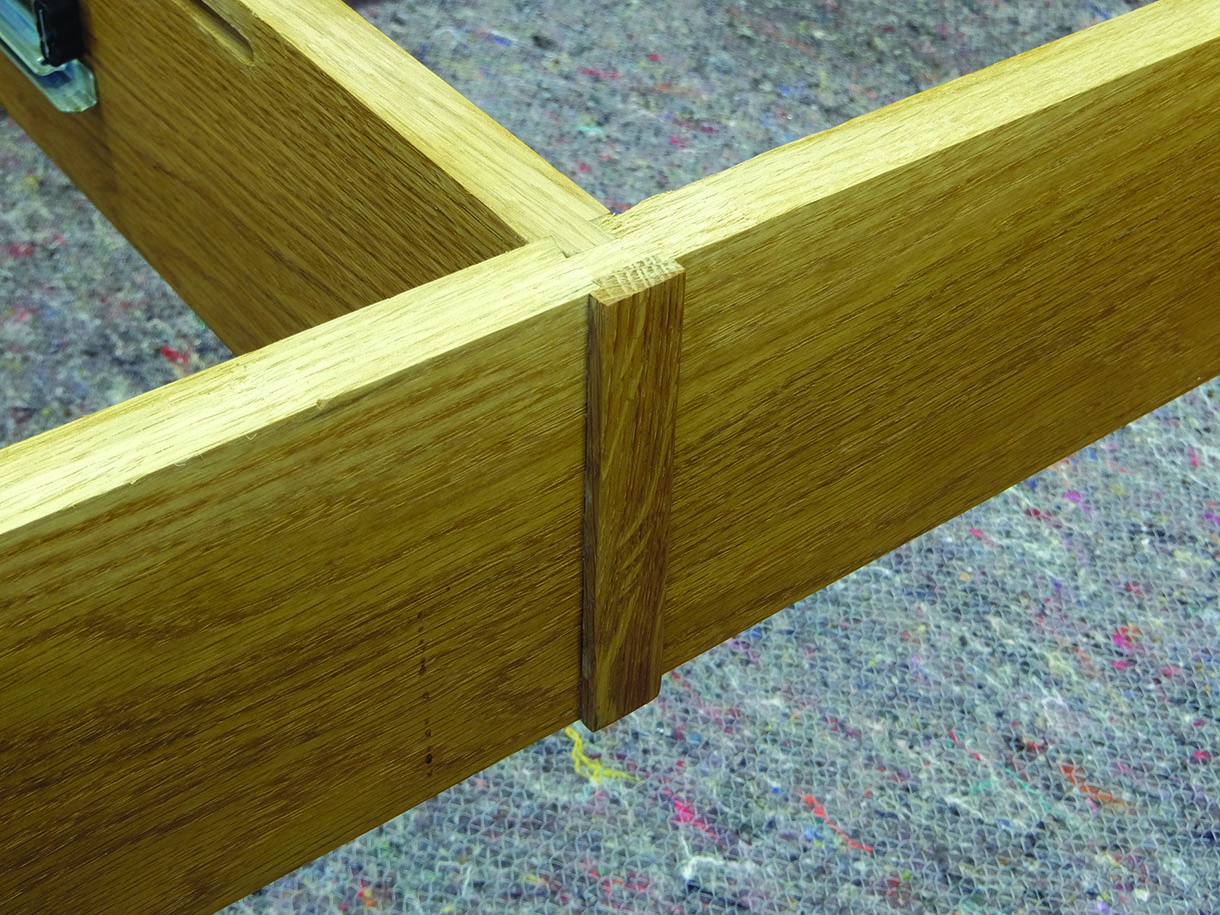
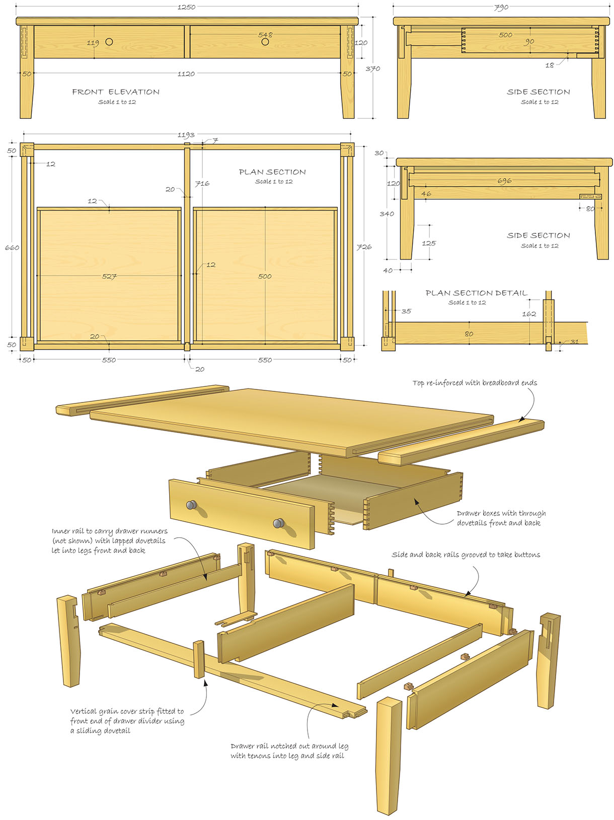
1. Having prepared the timber the back and side rails were joined to the legs with mortise and tenon joints. The front rail was tenoned into the front legs and the front of the side rails. The centre rail was joined to the back rail using a sliding dovetail. At the front, instead of showing end grain between the drawer fronts, a piece was fitted with the grain running vertically. This was echoed on the back rail and both pieces were fitted with sliding dovetails
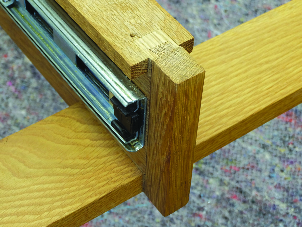
2. These were formed using a dovetail cutter on the router table
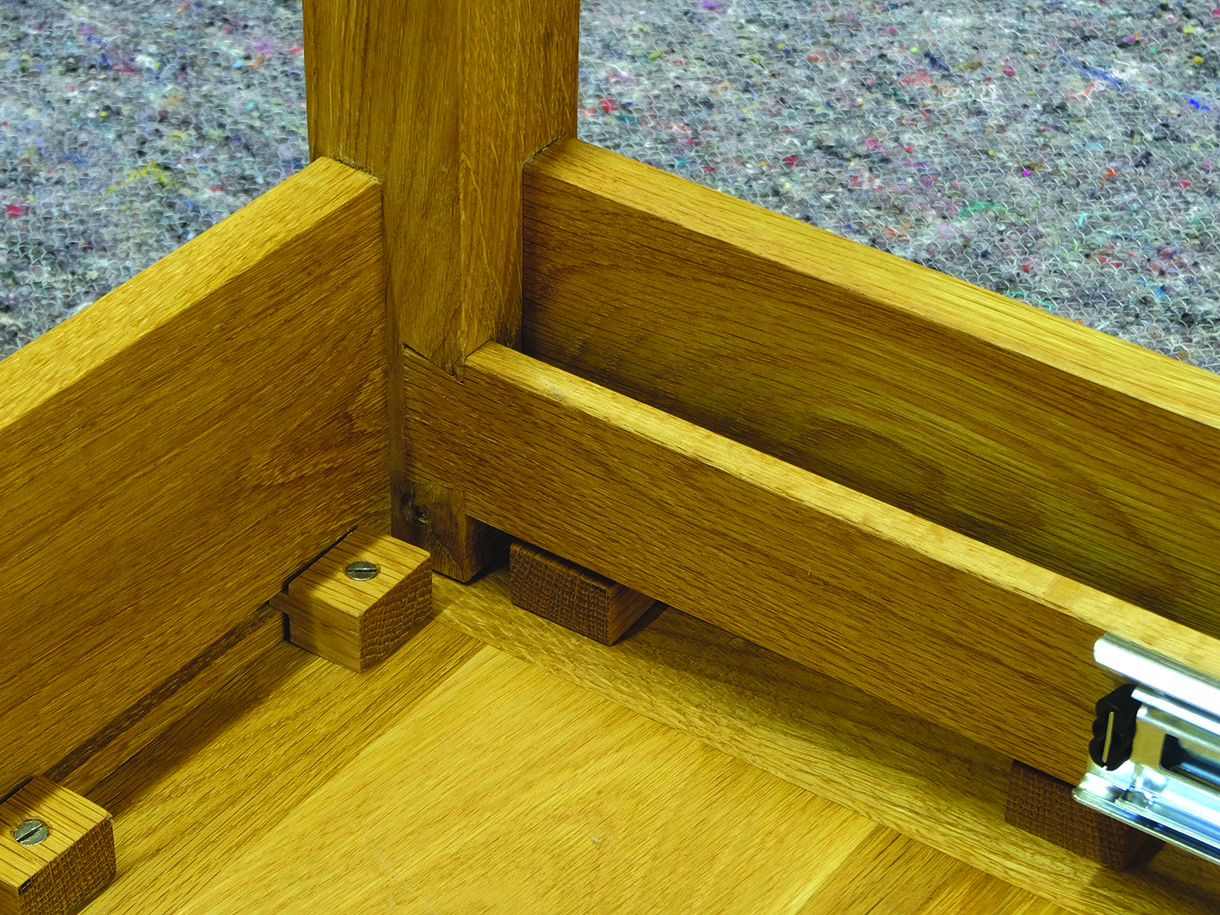
3. On the end frames an inner rail was fitted, with a lapped dovetail to take the drawer runners and a groove cut to take the expansion buttons that will secure the top
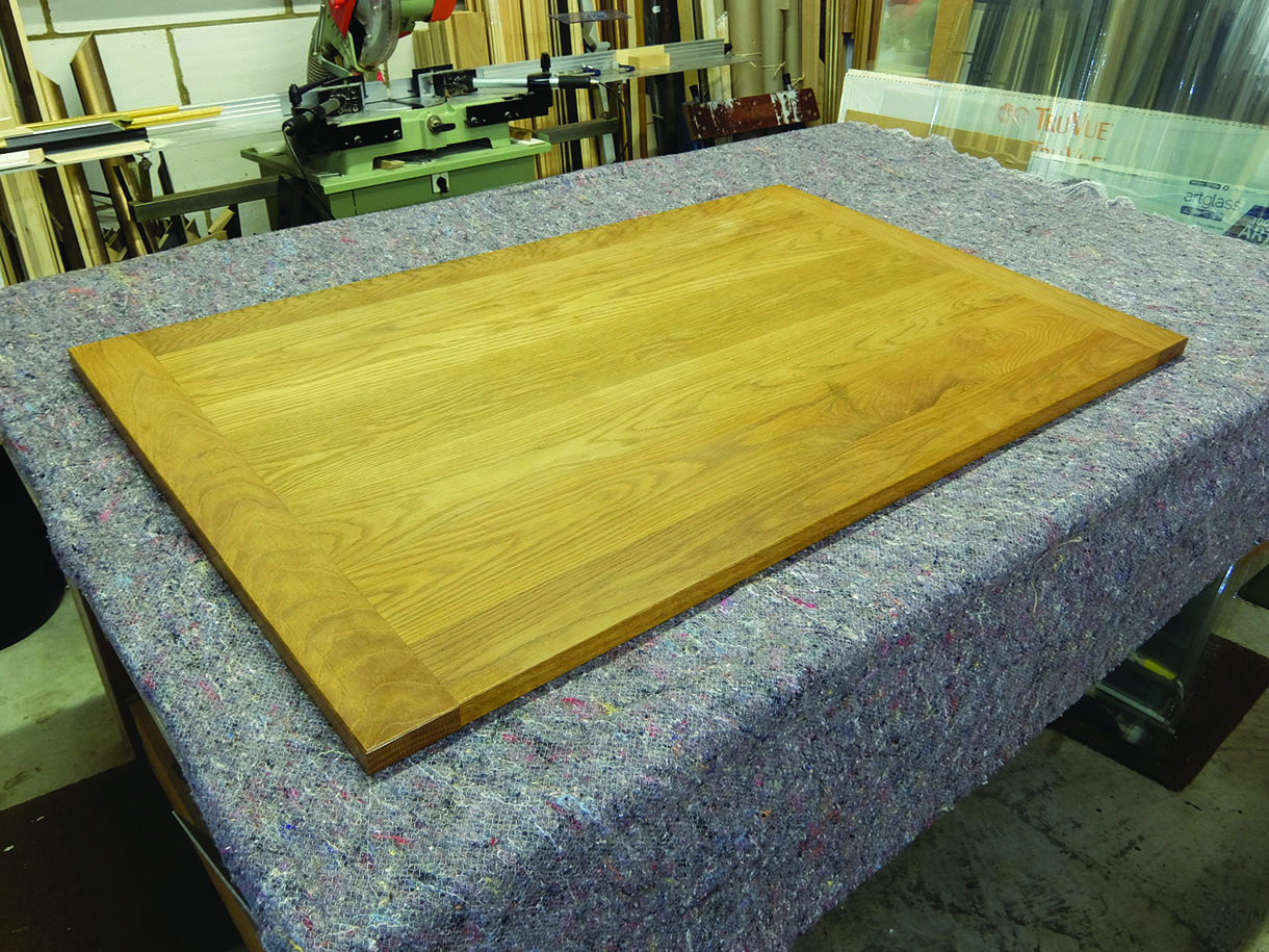
4. The top was formed with sections of timber of equal width, turned to alternate the direction of the growth rings. This helped keep the top of the table flat. The ends sections were then fitted to form a breadboard top
Hand-cut dovetails
I started by putting face marks on the outer faces of the drawer components top front-end of the sides and the top front and back. Then, 12mm in from each end (the thickness of the components) I squared a line round the timber. The end of one drawer side was marked out for the position and width of the tails and the lines squared across the end grain.
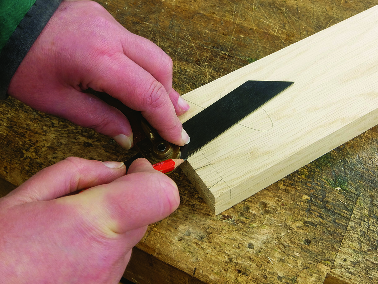
5. Using a sliding bevel set to a pitch of 1:7, the lines of the tails were marked
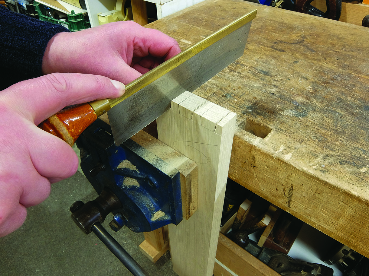
6. Keeping the top edges together, the other three ends were marked from the first end so the tails are all positioned the same. I scored the 12mm line across the tail sockets and then cut down the side of each tail on the waste side of the line
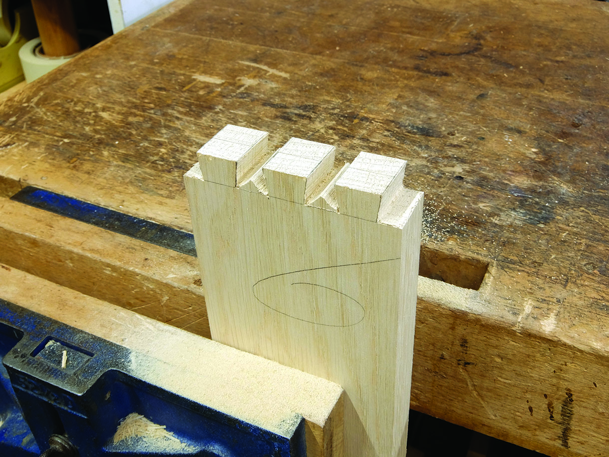
7. The end tail sockets were cut out square and by cutting at an angle I removed as much waste as possible. The remaining three ends of the two sides were cut to this stage
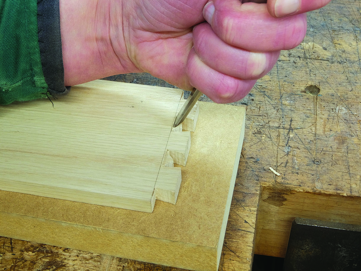
8. Next, I chiselled out a small amount of the remaining waste, back to the 12mm line. This creates a clean shoulder line to work to when trimming out the tail sockets
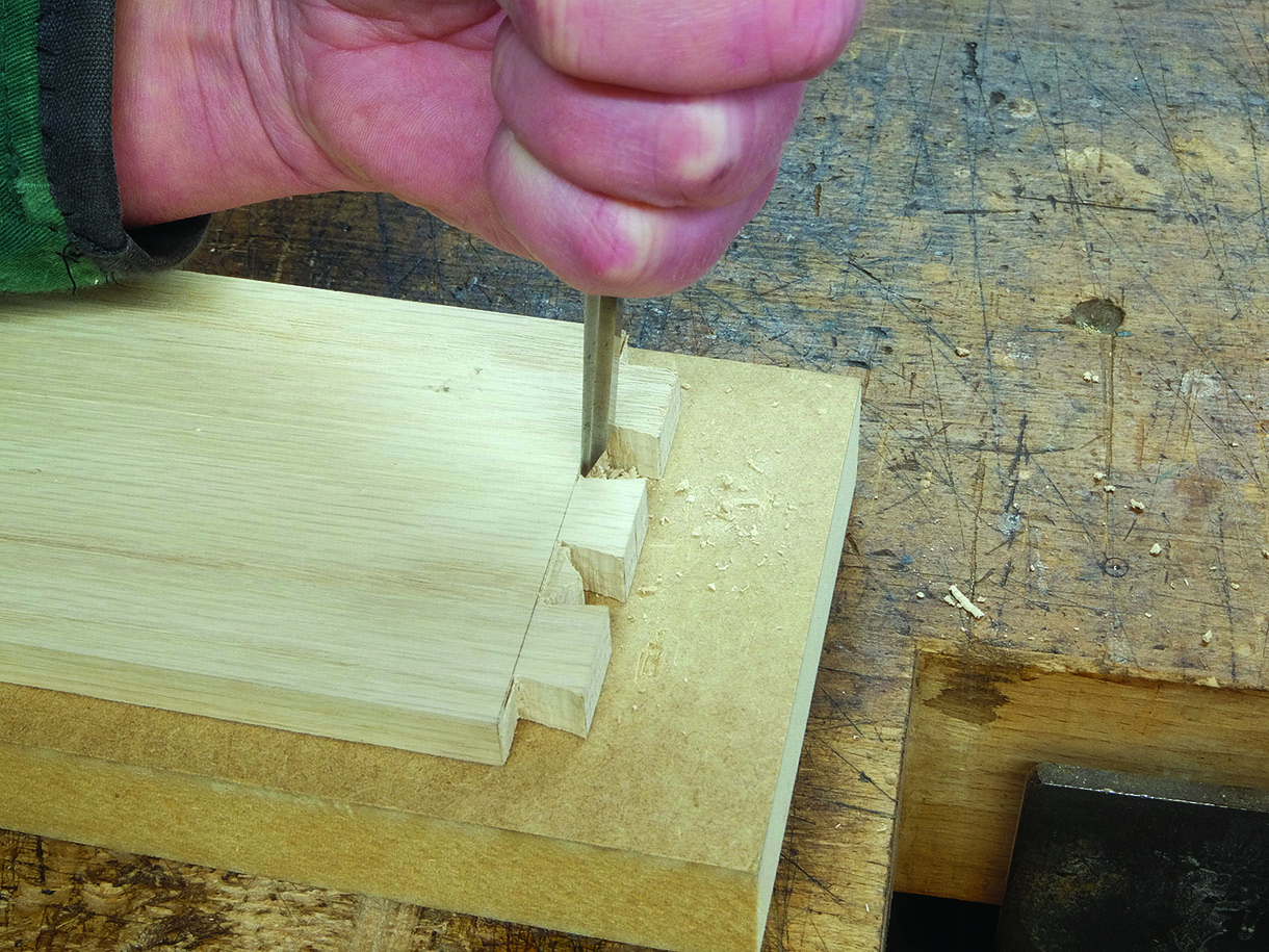
9. Working from both sides and keeping the chisel upright the remaining waste was cleared, making sure not to undercut the shoulder line
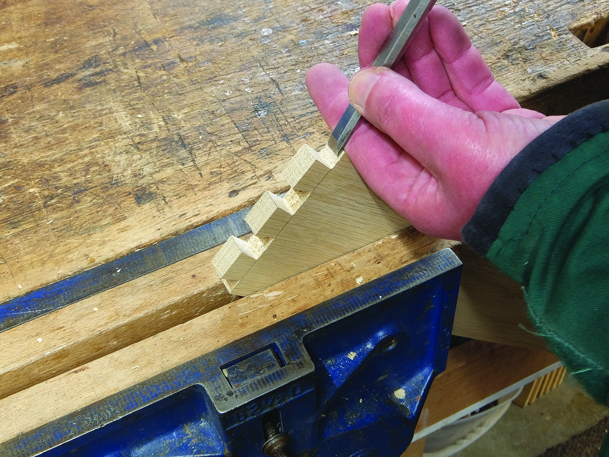
10. The outer tail sockets were trimmed to the three score lines and the shoulder line checked for square. The sides of the tails were then trimmed and squared
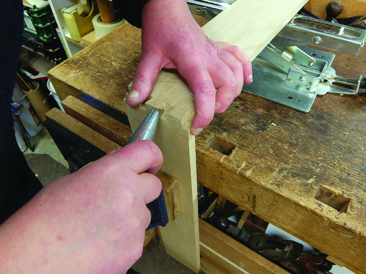
11. To mark the pins, the ends of the sides were, in turn, lined up on the corresponding corners of the front and back sections and the tails marked using a sharp knife. The same procedures were followed to cut out the line of the pins and the bulk of the waste. The pin sockets were trimmed up as before. Once the four sections of pins were cut the drawer carcass was trial fitted together and any further trimming up was carried out for a close fit, but not so tight that when the glue is applied the joints are too tight
Machine cut dovetails
There is more than one type of dovetail jig on the market, but I purchased the Leigh jig some years ago opting for this one as it could take a 610mm wide section. You can also buy a mortise and tenon attachment, finger joint templates and their own Isoloc joint templates (to make curvy joints) to work on the jig, making it more versatile. The jig comes with a very comprehensive instruction manual
to take you through the stages in far more depth than I can cover here.
One key thing is the guide-finger assembly has two rows of fingers. The straight side, when used with
a dovetail cutter will cut the tails. On the other side, the fingers are angled and combined with a straight cutter, will cut the pins. The scales denote timber thicknesses and it is best to have some test pieces available to trial the fit of the dovetails and make any necessary adjustments.
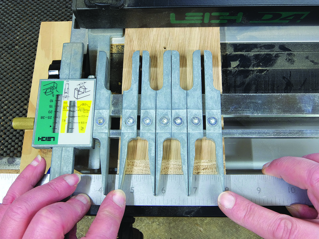
12. Having clamped the necessary spacer boards in place – these act as a waste support piece behind
the drawer components – the guide-finger assembly was fitted in the pin mode (the angled finger side), which allows you to adjust the guide-fingers. The two outer fingers were kept 3mm in from each edge
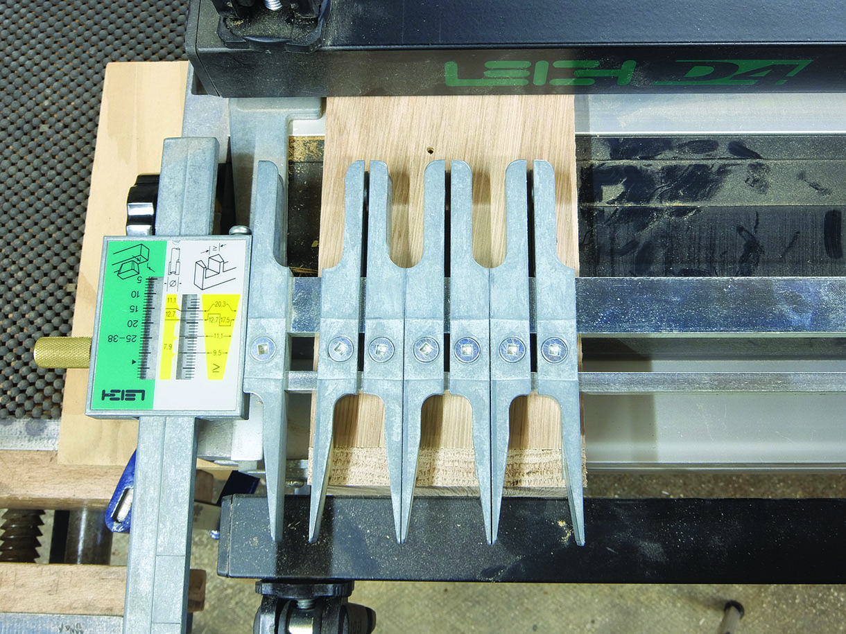
13. The remaining fingers were pushed up tight together, then the resulting gap was divided evenly to obtain the space between the two pairs of fingers, which were then locked in position. The remaining fingers to the right were locked off and act as a support for the router. The guide-finger assembly was then turned back over to the straight fingers, set to the correct measurement (this depends on the thickness of your timber) and locked in position. With the drawer side in the front clamp, with the inside face away from the jig and tight under the guide-fingers, the thickness of the timber was marked on the drawer side
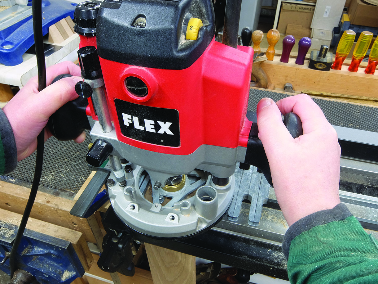
14. I then adjusted the depth of the cutter to the line. The cutter was guided around the guide-fingers using the correct size guide bush until all four sets of tails were cut
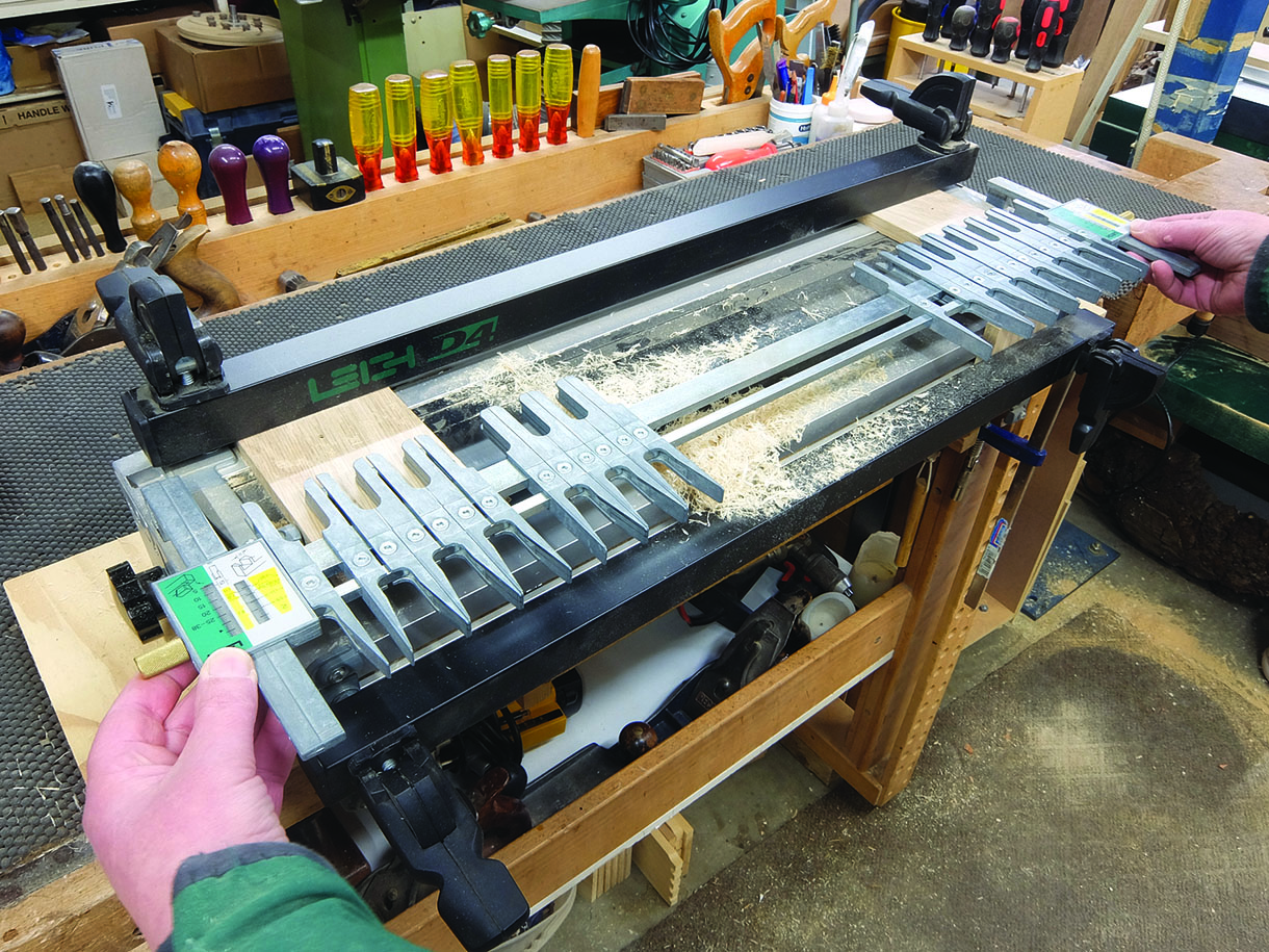
15. The guide-finger assembly was then turned back to the side with the angled fingers and the cutter changed for a straight flute. To cut the pins I worked with the outer face of the drawer front and back away from the jig. The thickness of the timber was again marked and the cutter depth set
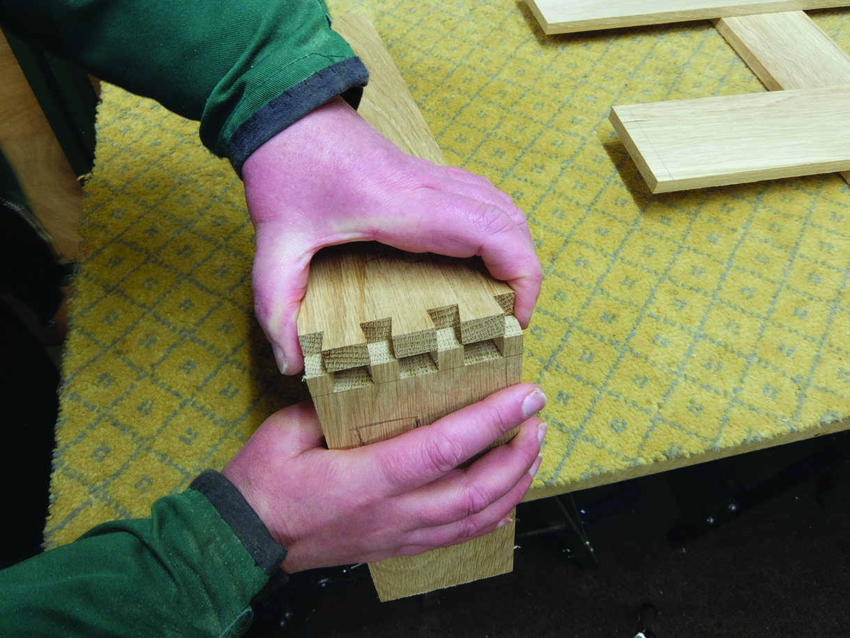
16. I set the measure gauge one division above the required thickness and cut a set of trial pins,
the finger assembly was then moved in further to the jig to reduce the size of the pins to make a good fit. The cutter was moved from left to right so the waste was removed in stages to reduce the amount of breakout
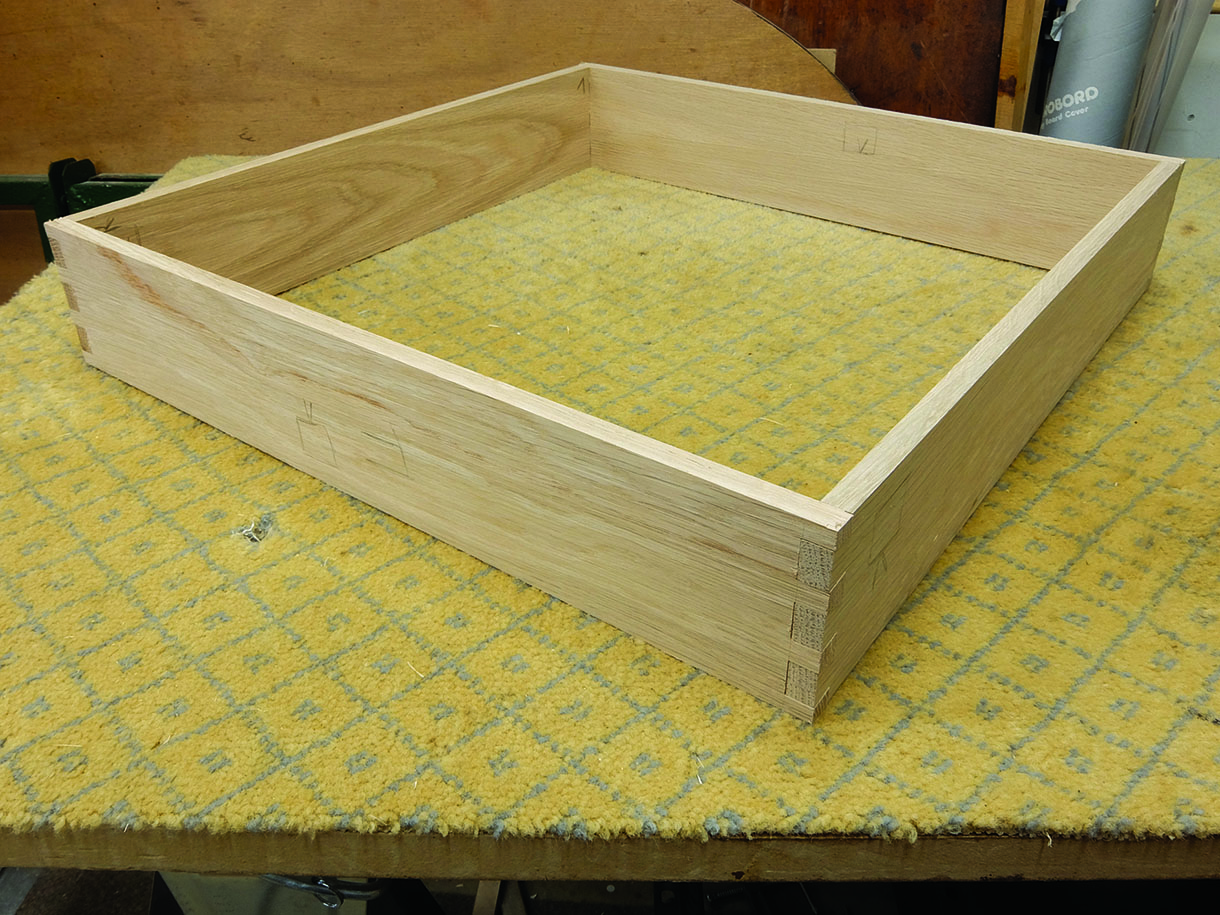
17. Once all the pins were cut, the drawer carcass was fitted together. With the drawer carcass formed, a groove was cut, stopped in from each end, around the bottom edge to take the bottom panel

