Richard Findley explores a traditional technique
When the Editor suggested I should take a look at therming, I knew exactly what I would make. From time to time I am asked if I can make replacement stair spindles that are ‘square turned’. I have often thought I could give therming a go, but generally turn the work away as I don’t feel I can invest the time into the necessary research and learning curve that would allow me to do it properly. For many years these spindles have been made commercially using rotary knife lathes but this article gives me the perfect opportunity to see if therming could be an option next time someone approaches me with a potential commission.
The theory
This project is going to involve making a jig. The jig involves two wooden faceplates which fix to each end of a group of spindles, forming a kind of drum. The jig means that a set of spindles are all turned at once, fixed to the outer edge of the wooden faceplates, meaning that each spindle will appear to have a flat face, although it does in fact have a slight curve which matches the diameter of the jig. I suspect this project could be one of my biggest challenges yet, with no part of this complex process appearing particularly simple or straightforward, but we shall see!
The plan
I need to do some research. I’ve seen pictures of therming, both of the jigs and the end results, but have never seen it done in real life. There are a few options available to me as far as the jig goes and so I need to organise my thoughts and the design before I do anything. Once I’ve pinned down the design for the jig, it will be a case of fastening the spindles into it securely and turning the spindles mounted in the drum. As I turn, each face will be turned and rotated four times before it is complete. I will make a copy template as I would for a normal reproduction spindle job and hopefully transfer the positions of the details to the drum. I imagine getting all of the details correct on all of the faces will be a challenge, as will cutting them to a consistent depth. There may also be vibration and chatter to deal with, but until I begin, I won’t know for certain.
Research
My friend Mike Wood, a production turner from Bedfordshire, has experimented with the techniques of therming, so it makes sense to talk to him as my first port of call. Mike was kind enough to share pictures of his jig and details of how he’d made his thermed spindles. As I draw on this information and reading other articles in books and online, a picture begins to form as to how I will make the jig. There is one thing that I am struggling with though: most of the jigs in my research have a central column, which adds stability and joins the two faceplates together, however for the design I have in mind it shouldn’t be needed. I am very cautious whenever I feel I’m going against an established norm because it rather suggests I’m missing something, but I decide to proceed with my plan, without the central column, and if I find I do need it, I can always add it later.
Health and safety
Therming is an advanced technique which could potentially be dangerous. Throughout the process I was comfortable with everything I did, but if at any point you don’t feel comfortable about doing any of the operations involved, find another way. Ensure all timber used is sound and free of faults, including the spindles themselves and the plywood faceplates and ensure the spindles are securely fitted into the faceplate discs. A full face shield should be the minimum protection worn throughout this turning operation.
The jig
Mike’s version of the jig has thick MDF faceplates which are routed using a box jig, but are open, so the spindles sit in the grooves and are secured in place with a large Jubilee clip. This design does need a central column because there is nothing holding the discs in position. My plan is to rout a recess or housing into the face of the faceplates, around half the depth of the material, giving a tight fit for the ends of each spindle. I then plan to fasten a screw into both ends of the spindles to secure them in place. Because each of the spindles will be securely fastened at each end, this should mean the central column won’t be required.
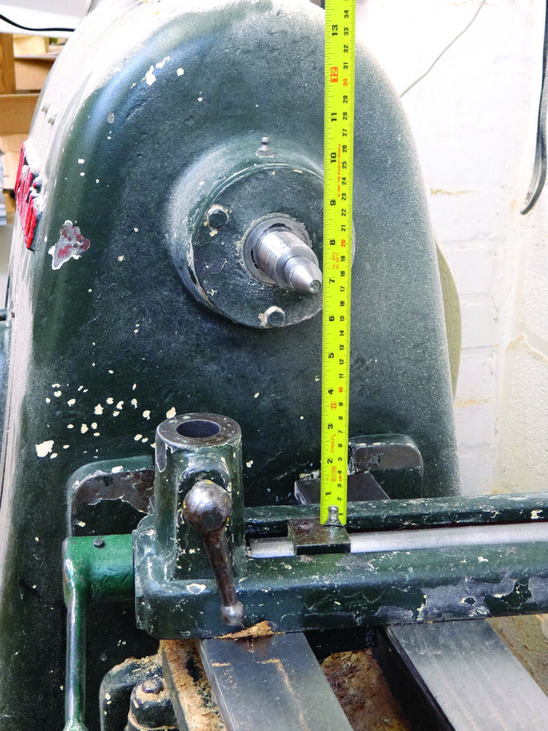
It makes sense to me that, to achieve faces on the spindles appearing as flat as possible, I need my drum to be as large a diameter as possible. My lathe swings 400mm over the bed, but I need to get the banjo between the bed and the work, so I settle on 310mm diameter for the drum. I have some 18mm plywood which fits the bill for my faceplates. I mark the discs cut them out on the bandsaw, before mounting them between centres on the lathe to true up the edges and make them both the same diameter.
Marking out
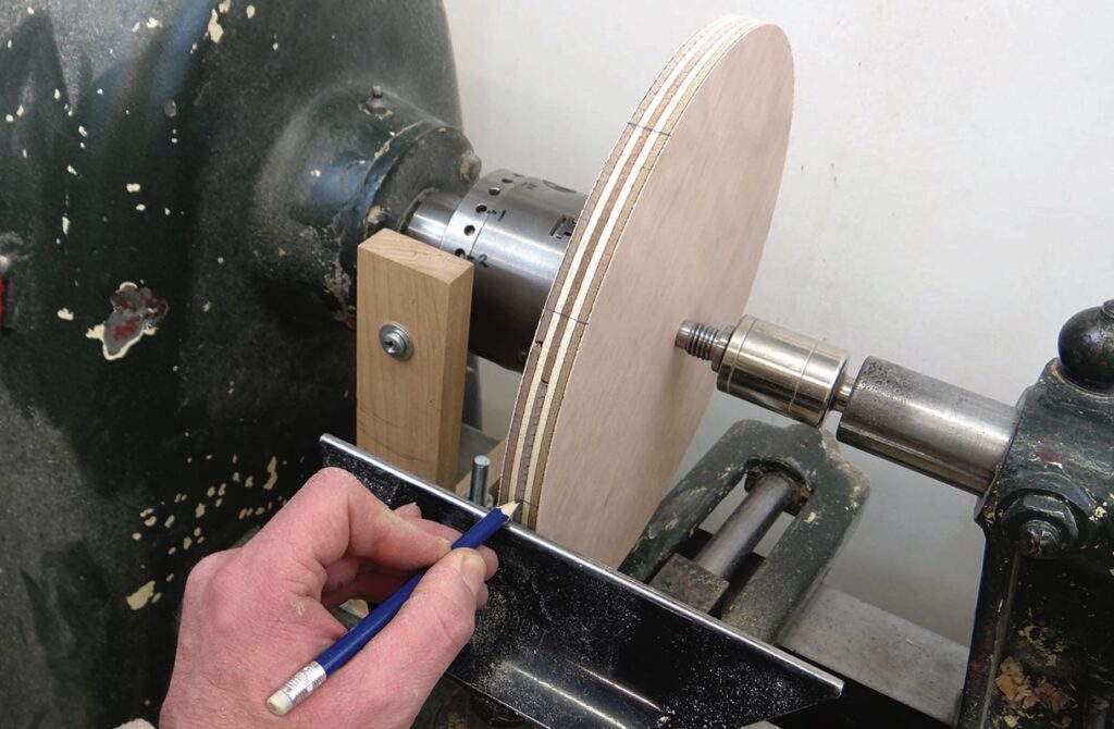
I decide that 12 spindles would be a good number to work with. I have no particular evidence to suggest this is a good or bad number to use, but I find 12, being the numbers on a clock face, easy to visualise. Mike also used 12 spindles on his version, which reinforces my thinking. I hold a drive centre in the chuck and grip the plywood faceplates between centres, locking my workshop-made indexer in place and simply drawing a line at centre height with a pencil resting on the toolrest.
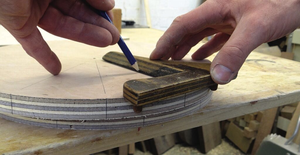
With both faceplates marked on their edges, I use one of my Grandad’s old tools that I affectionately call a ‘circle-square’, because it draws a line, square – or perpendicular – to a curved edge, although I suppose technically it would be called a centre finder. With this I transfer the edge marks across the face of the discs.
Routing jig
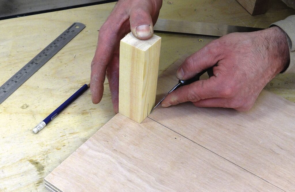
I next need to rout a housing for the spindles to fit into. I prepared the softwood spindles to 35 x 35 x 650mm long, which is short for modern spindles but well within the realms of Victorian spindles that may well have been made like this. Using an off cut of the spindles I use a knife to mark the position of the spindle on the
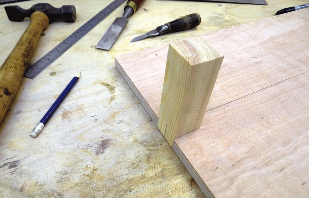
centre line of another piece of plywood. This will form the base board of my router jig. I cut the marked area out on the bandsaw and pare it to a tight fit with a chisel.
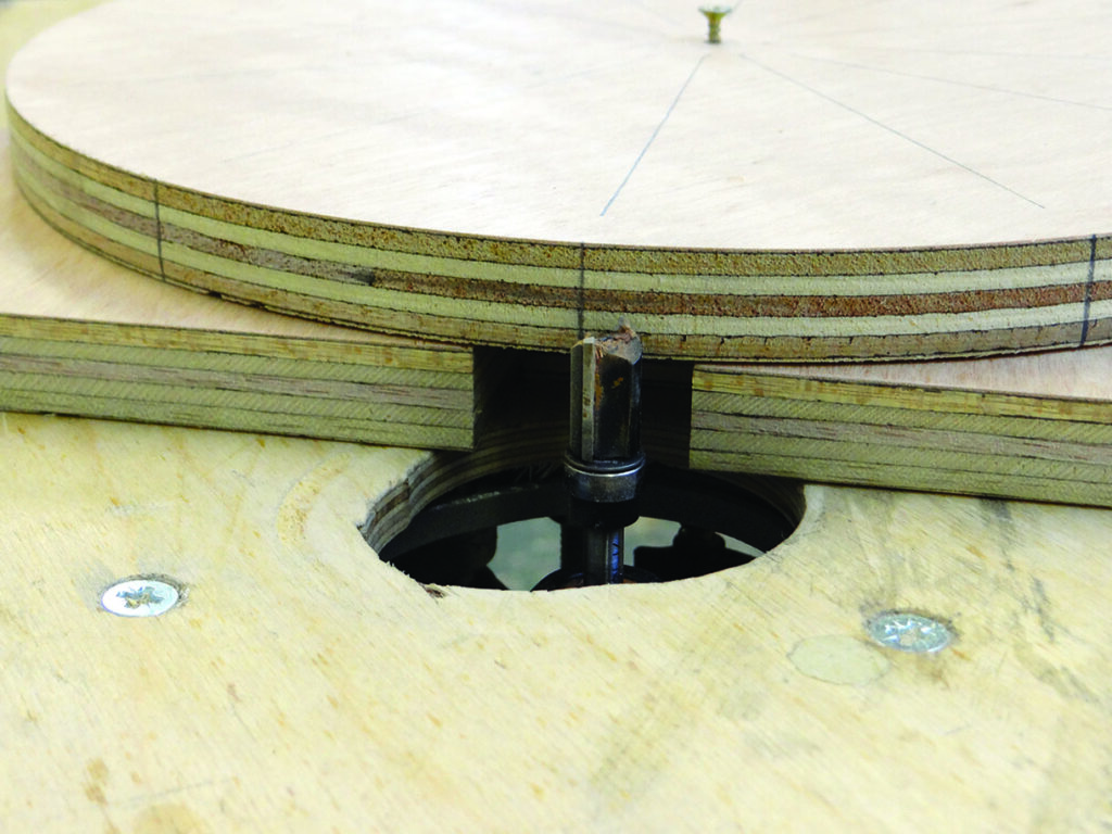
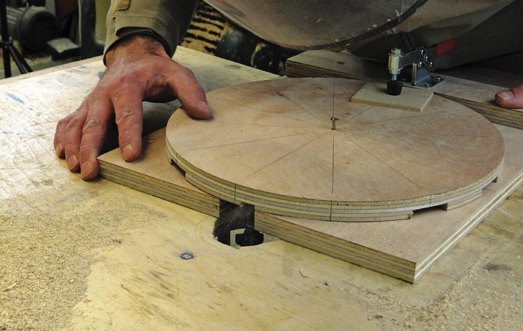
I will use a straight router cutter with a bearing guide, the bearing will run on the cut out I’ve just made, I next need to secure the faceplate disc to the base board. I like to keep my jigs as simple as possible, it is so easy to over-complicate jigs like this. I simply use a screw through the centre of the plywood disc, which allows the disc to rotate evenly over the cut-out in the base board. I fasten a toggle clamp at the lower part of the jig which will lock the disc in position. With a little trial and error I draw lines on the jig which enables me to rotate and position the disc in just the right place to machine each spindle housing.
To ensure there isn’t too much vibration from the cutter, I take two passes over the router to form each housing and the whole operation goes as smoothly as I could hope for. The toggle clamp securely holds the disc in place and the disc rotates smoothly on the central screw, lining up each time with my marks on the base board.
Fixing the spindles
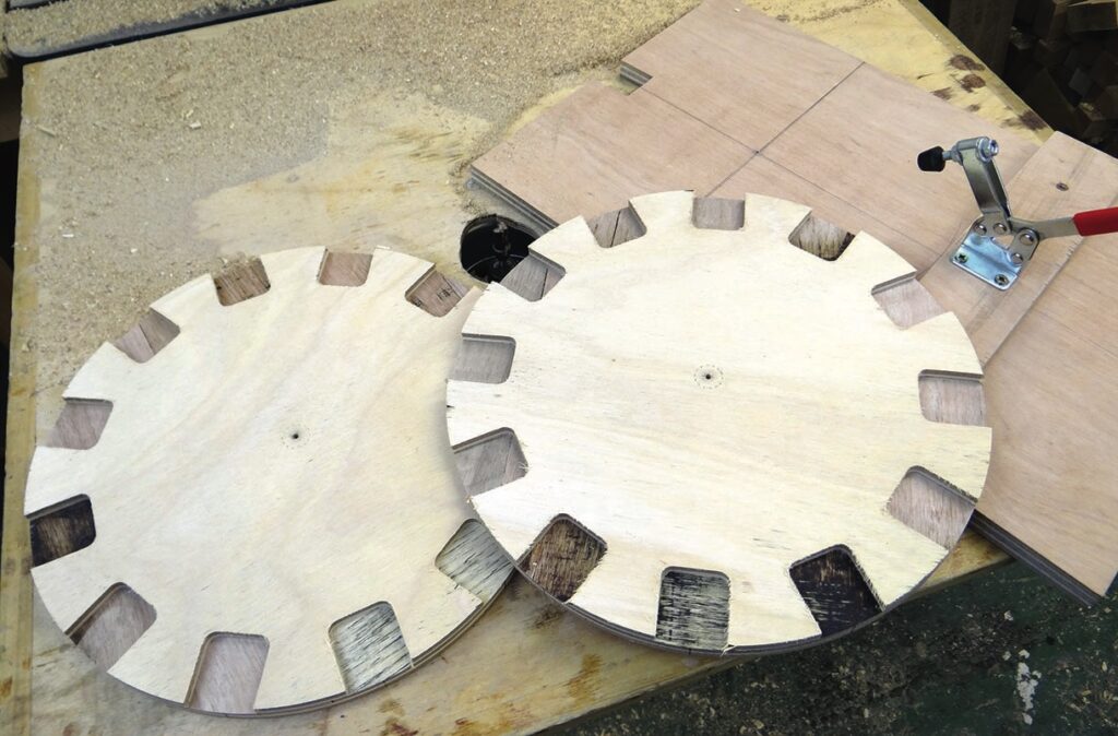
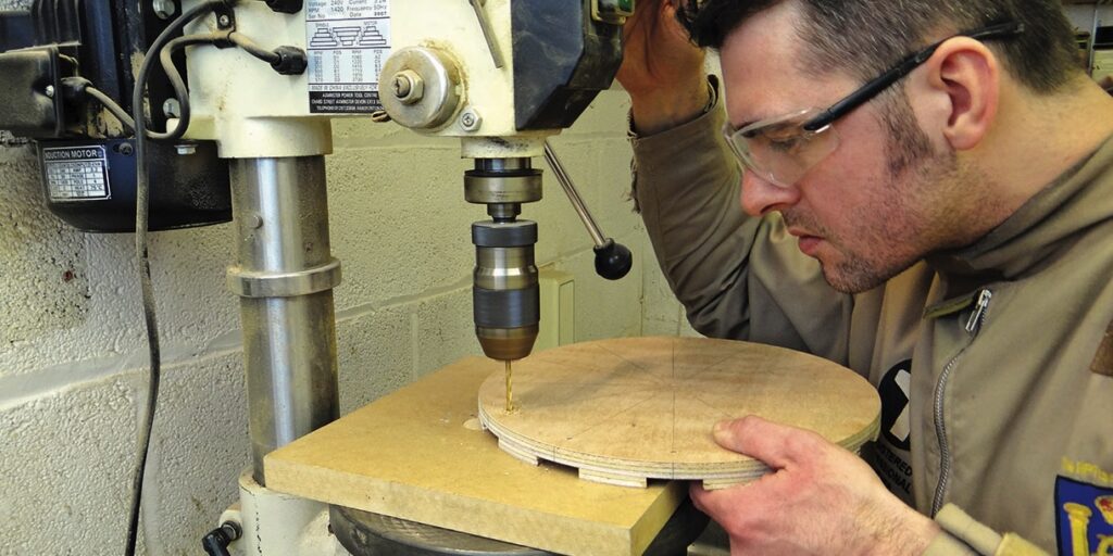
After a little measuring and experimenting I settle on a position to pilot drill the screw holes in the plywood discs. Initially I thought I would need to square each of the housings with a chisel – the router naturally cuts them with rounded corners – but after a trial, I find the spindles fit quite nicely in place with a little persuasion from a hammer, and only slightly mark the corners of the spindles. If the spindles were hardwood this probably wouldn’t work, but pine does have its advantages! I mark the distance from the edge with my marking gauge and drill them on the pillar drill.
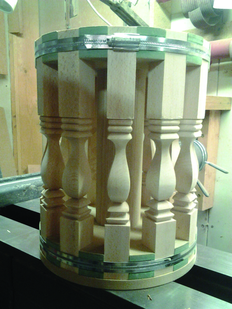
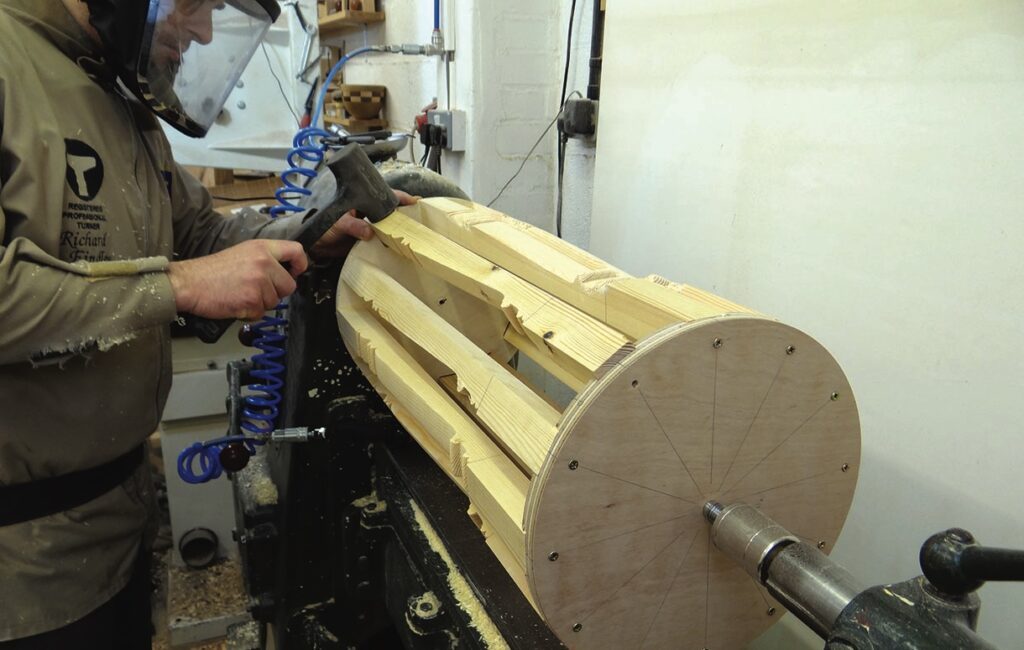
I’m now ready to assemble the drum. I tap each spindle into its housing in one of the plywood faceplates, then place the second disc on top, adjusting each spindle so it lines up with the routed slot, tapping it all into position with my hammer. Happy they are positioned properly, I drive a screw into each of my pilot holes, securing them in place. I then fasten a faceplate to one end. The whole drum then simply screws onto the spindle nose of the lathe and the live tailstock centre holds it all centrally. Spinning it round by hand, I’m pleased with everything so far.
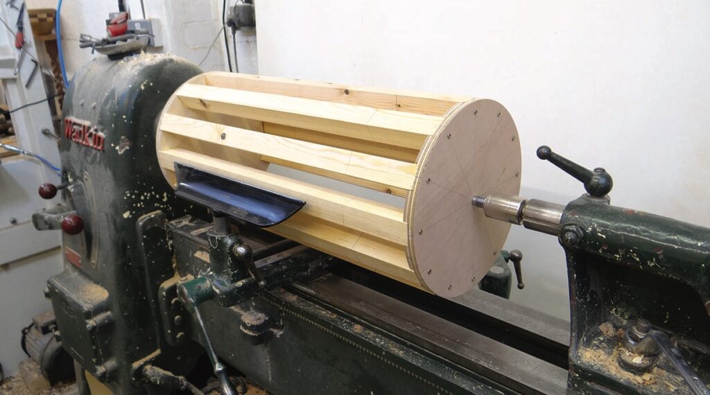
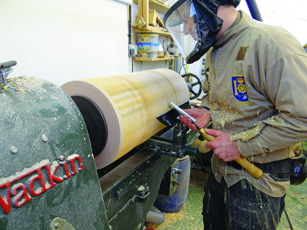
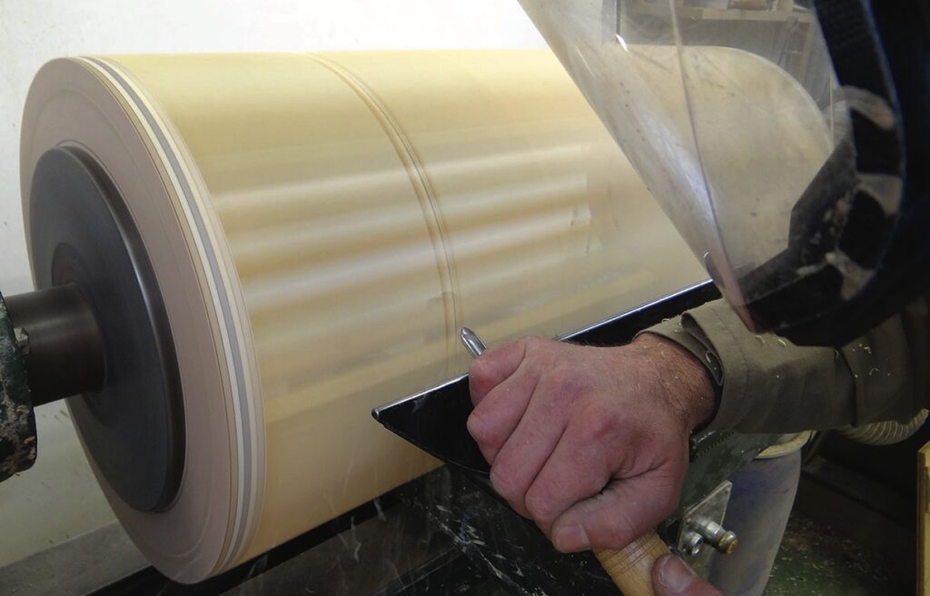
Turning face one
I marked the extremities of the turned section before mounting the spindles in the drum and these marks are very clear to see as I spin the drum. As is best practice, I start at a low speed and build up to the fastest I can safely work at. I am disappointed that 500rpm is as fast as I can run without vibration. This is the first time I have wanted electronic variable speed, as my next speed selection is 750rpm, which vibrates far too much, even on the big lump of cast iron that is my old Wadkin.
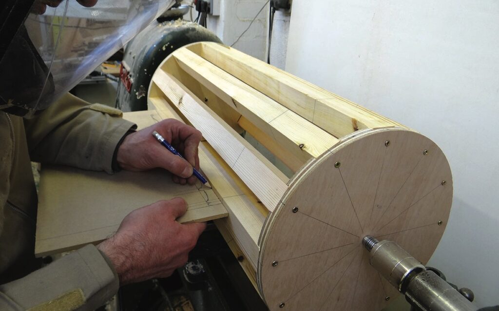
I make a copy template, just as I would for a standard replacement spindle. I try, perhaps foolishly, to mark the positions of the details with the drum spinning, but unsurprisingly the lead of my pencil lasts mere seconds before snapping off. I decide to mark the spindles individually, but as this will be rather tedious I start off just marking two opposite spindles. I am pleased that I can see the lines well enough to begin turning, but of course more marks would have been clearer.
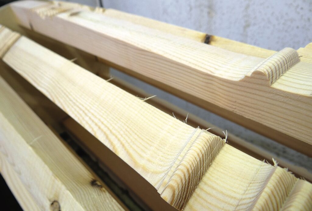
I make a few tentative cuts with my spindle gouge, regularly checking how it looks. Pleased with the initial cuts, I work along the whole drum, turning the necessary shapes. There is clearly a little run out as some spindles show slight flats, where others don’t, but I turn past these flats until I am ready to sand. Because the speed is just 500rpm, the finish from the tool is not as good as I would like, I hope sanding will improve the surface.
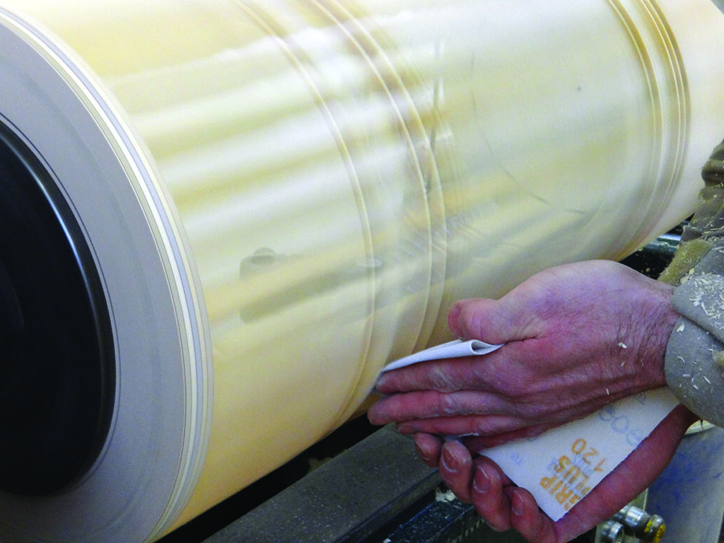
Sanding is done with great care. Initially I use a long strip of abrasive which gives good coverage while keeping my fingers clear of the drum but I need to fold the abrasive and carefully use it in a trailing action low down at the front to sand the details. Unfortunately, because of the gaps in the drum, I am not able to apply a great deal of pressure to the abrasive, which means it is much less effective than it would be on a standard spindle.
Turning face two
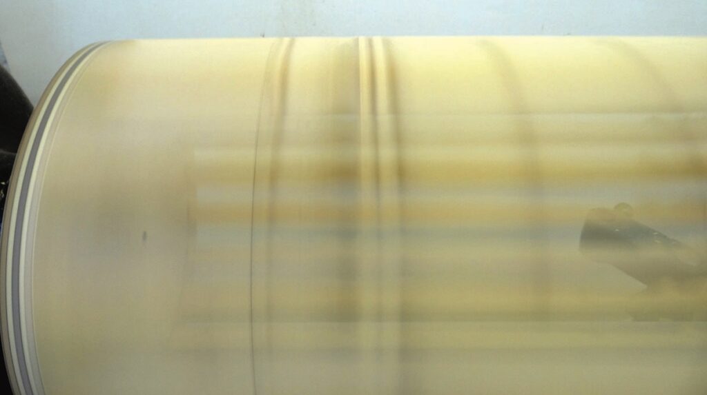
Because the turning process causes some break out at the top of each spindle, I decide to rotate the top edge toward me, meaning any break out from the previous cut will be removed by the next cut. I remove the screws and each spindle in turn, which are reassuringly tight in their housings, rotate them 90° and tap them back into place using my dead blow mallet, which I decide is a better option than my hammer as it doesn’t mark the spindles.
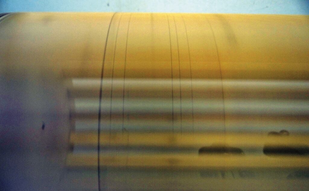
I start the lathe and can see a shadow of the turning, which means I don’t have to re-mark the detail positions. It is all rather blurred though, so regular stopping and checking is essential to ensure the cuts line up perfectly with my first set of cuts. Face two is soon finished and the spindles can be rotated again for faces three and four.
Turning
Several factors make the turning a little more tricky than usual. Firstly, the shear diameter of the drum means I am essentially turning a 310mm diameter spindle, which means all of the normal forces involved in turning increase, reducing the margin for error. This means I don’t use my skew as much as I would for a standard spindle, and gouge cuts are all made cautiously as what would be a small catch on a standard spindle becomes a large catch on the large drum. The low lathe speed is also rather frustrating, meaning that all cuts have to be made slowly and deliberately in an attempt to achieve the cleanest cut.
On the positive side, at no point do I experience any chatter or vibration from the individual spindles or the drum as a whole. I am also pleased that my method works well without the need for a central column.
Finishing off
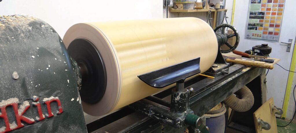
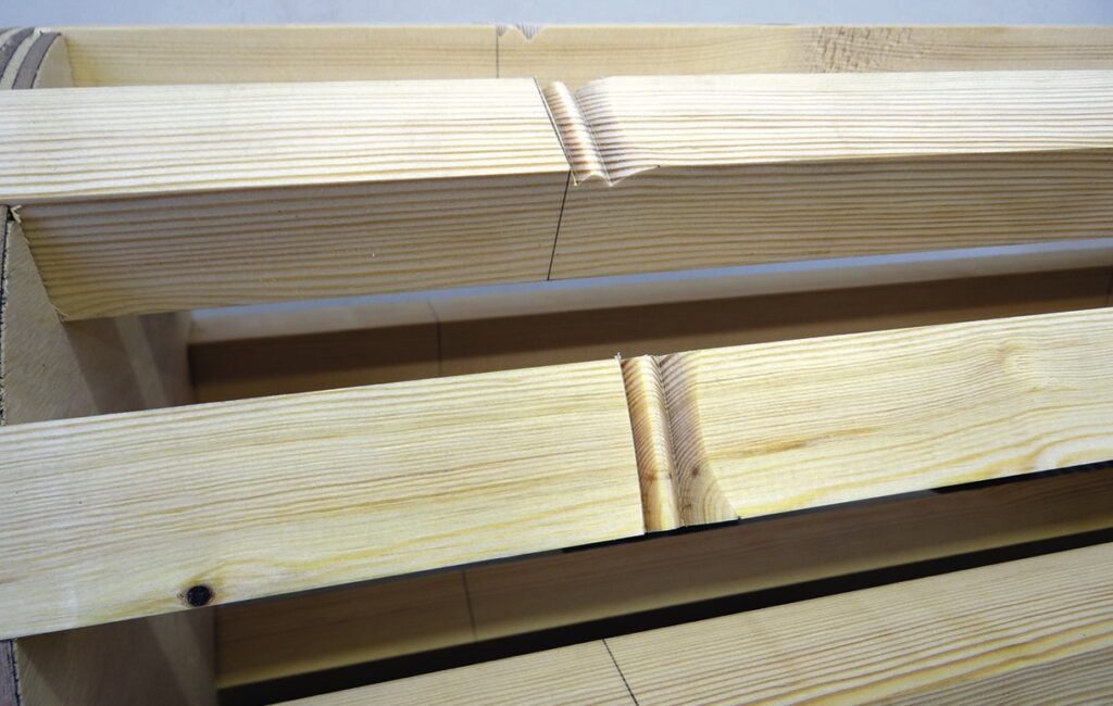
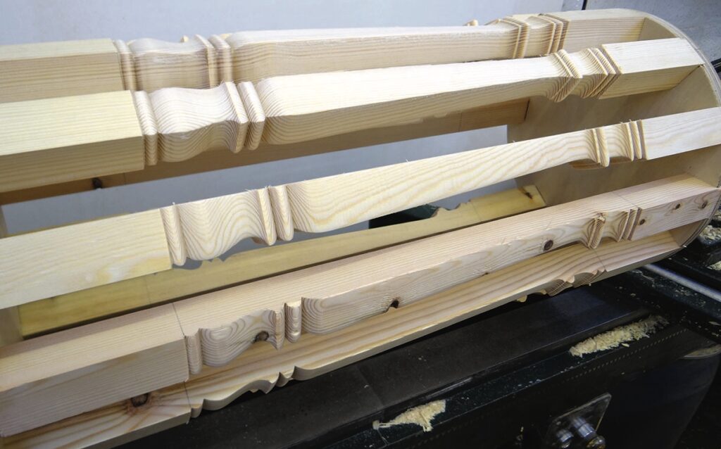
The final face is surprisingly quick to turn, partly because I’m beginning to get into the swing of things and partly, I suspect, because there is much less material to remove on this last face. As before, I regularly check each detail as I turn to ensure it lines up well with my previous cuts. When the turning is finished and
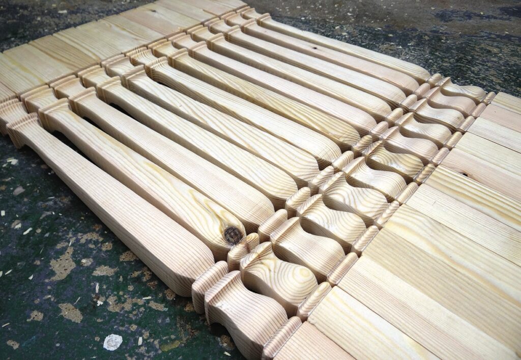
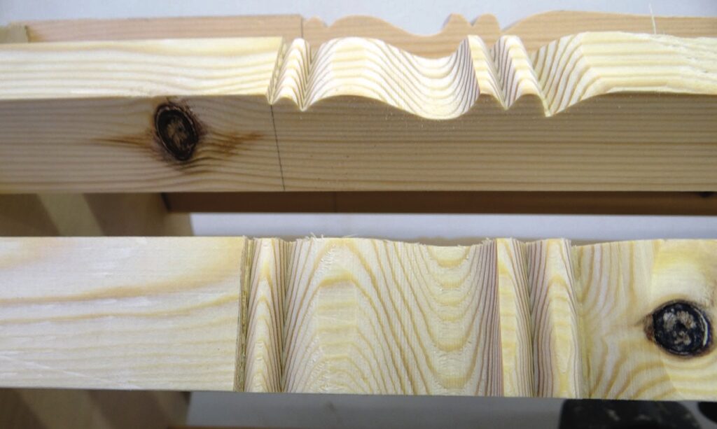
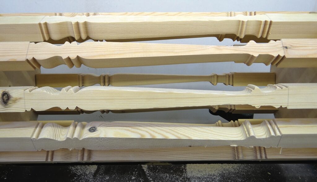
I stop the lathe and stand back to look at my work, it is clear that I have managed to cut at least one of the faces much deeper than the others. It seems the first face needed much shallower cuts, but as I was essentially guessing at the start, this isn’t that much of a surprise, but is disappointing. I remove the drum from the lathe and stand it up the right way, despite the obvious unevenness of the faces and some breakout on a few of the spindles, the overall look is pretty much what I was aiming for.
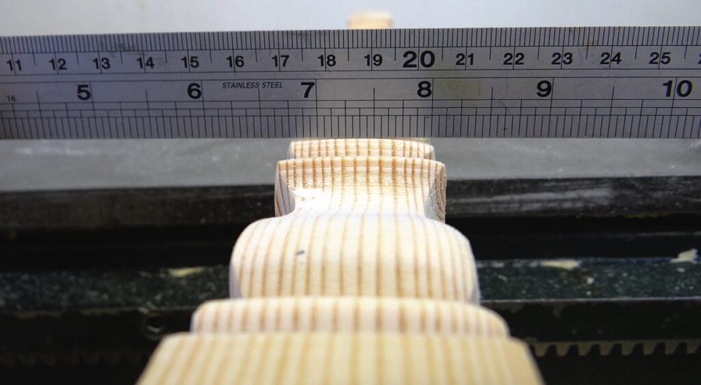
I am interested to see just how flat the square faces are. I lay a ruler across the face, which shows a definite curve, despite the square look they have from a distance. The diameter of the curve matches the 310mm diameter of the faceplates. A smaller drum would have most likely been easier to turn – putting the spindles closer together and being able to turn at a higher speed – but the faces would have been more curved. I wonder if this would have been more noticeable? The lower shape is quite even all around but at the top of the taper was where the problem is most obvious.
Conclusion
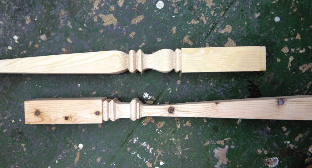
For a first attempt I am pleased how these turned out, but they aren’t good enough to sell. I am more than happy with the way the plywood faceplates performed and despite my concerns about going against the norm by leaving out the central column, it wasn’t needed with this design.
The biggest issues were controlling the depth of cut and reducing the breakout on the top edge of the spindles. If I had an original to copy, setting the depth would probably have been easier, as I would have been able to compare my progress with the original. As for the breakout, It might be possible to add some sort of in-fill piece between the spindles but this would add a huge amount of work to the whole set up. Perhaps a slight bevel added to the vulnerable edge might help, but again this would add a huge amount of work to the job. A smaller diameter drum would put the spindles closer together and allow a higher turning speed which may also help. More spindles in the drum could also be an answer.
In all I have learned a lot from this fascinating experiment and I think if I were to do this again, it would certainly be more successful, but I don’t think I’m going to be offering square turned spindles for sale any time soon!