Derek Jones weighs up the cost for a small-scale batch production run of octagonal components
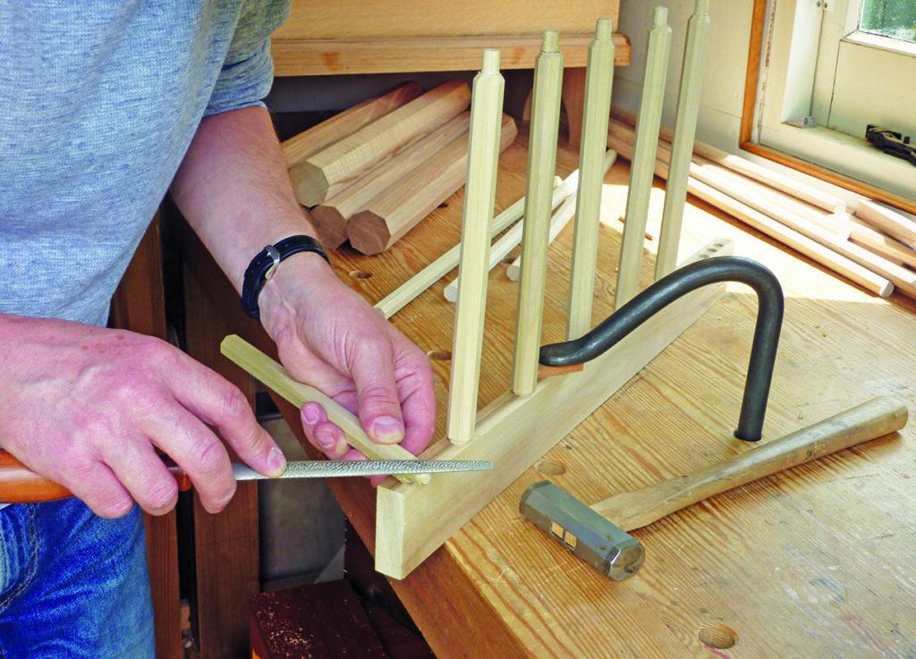
Handtool work is a bittersweet pill for me as it involves the things I like and dislike the most about woodworking; making things blunt and making things sharp. In fact just like a balanced diet, a more accurate metaphor for life is hard to imagine. While firing up an electric router may not be everyone’s idea of fun, there’s no denying that on occasion they provide a faster route from A to B and for a lot of us that edge translates into a process that’s commercially viable. Before we go any further it might help to identify in the first place the operations that require a disproportionate amount of time and attention. When the removal of material is the basis for nearly all woodworking processes there’s no easy answer until you factor in the volume of material being removed. Whether your output is for commercial gain or not, nobody likes to waste time on the mundane stuff if they can avoid it and that’s the premise for this article. For the small workshop, investing in a router table probably makes more sense than having a bandsaw, a tablesaw and maybe even a planer-thicknesser. These labour-saving devices perform some very specific tasks of which none are particularly unique or bespoke. And as most timber suppliers are happy to perform these tasks for a modest fee, it often make sense to pay them to do so.
A table-mounted router will allow you to perform a number of accurate and repeatable processes quickly and to unique dimensions and specifications. Perhaps one of the most frequent being running lengths of identical moulding or profiles to matched components. In this article we’re going to look at a technique for rapid stock removal that also results in a decorative component with a few added benefits for further shaping and future projects. Making things out of wood sometimes involves taking a piece of timber that’s not quite straight and making it straight before turning it back into something that’s not quite straight again. This technique works in much the same way; we start off with something round, make it square and then make it nearly round again. A more fancy word for it might be ‘octagonalisation’.
Squaring up
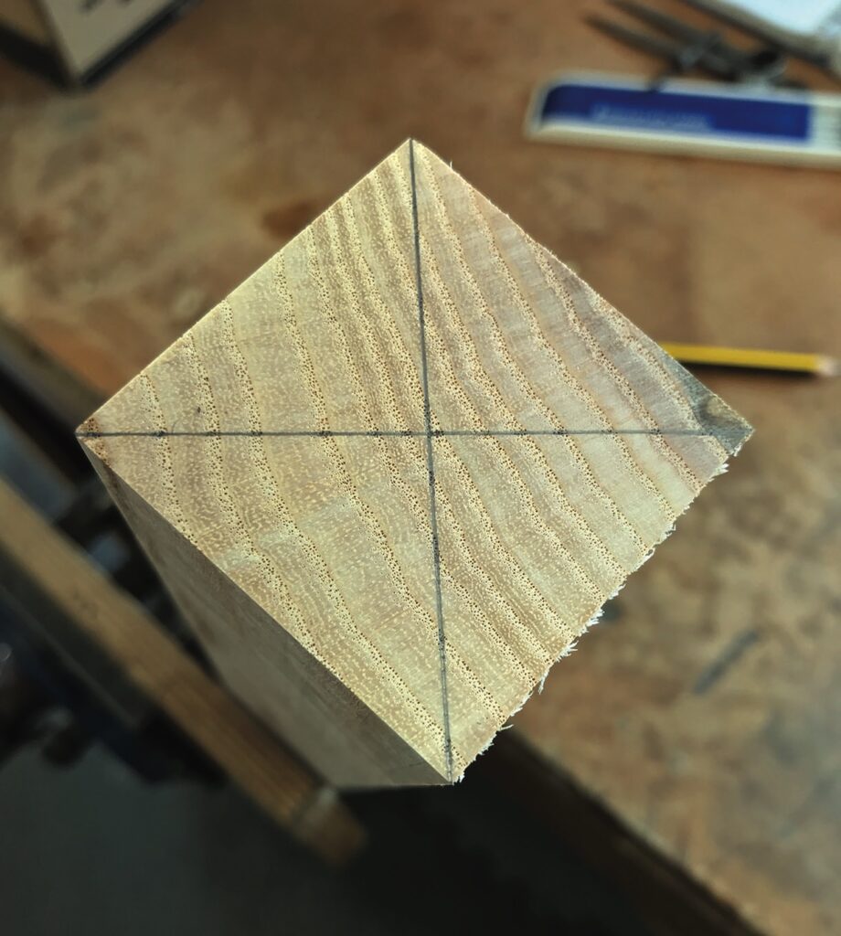
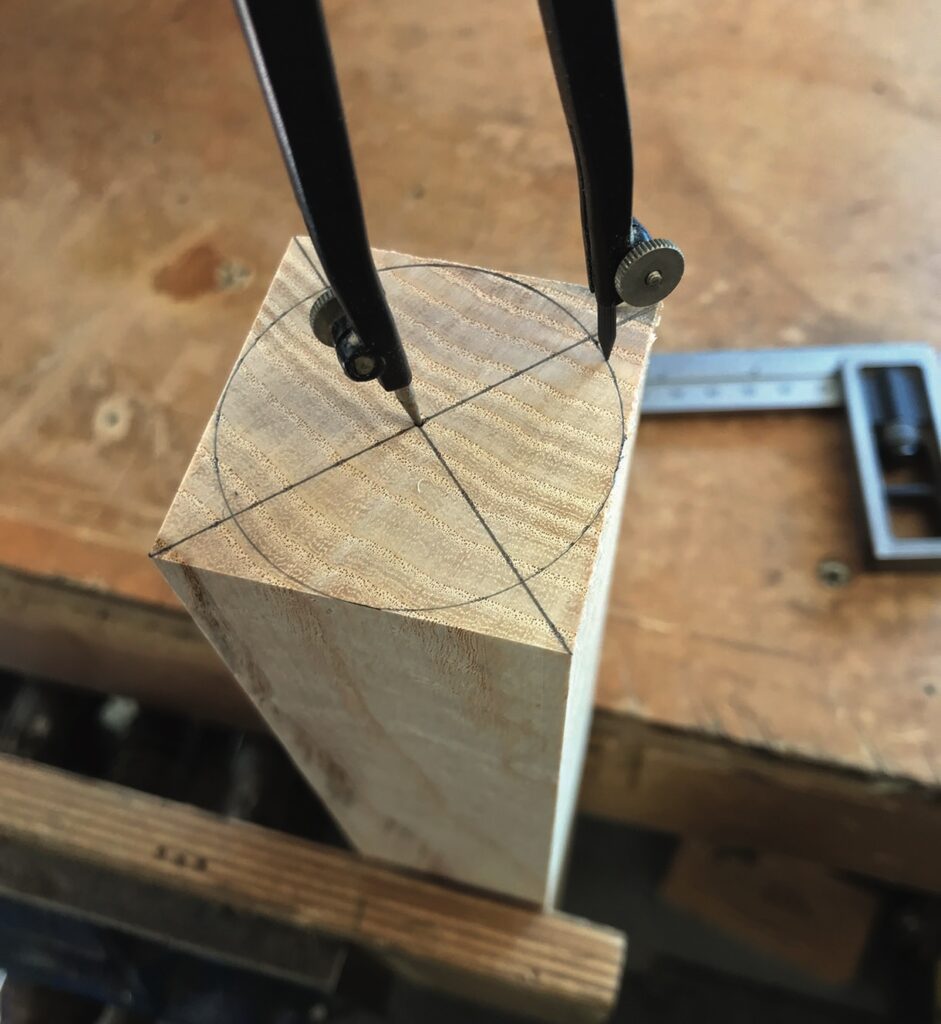
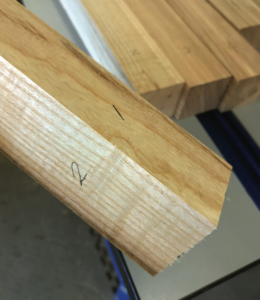
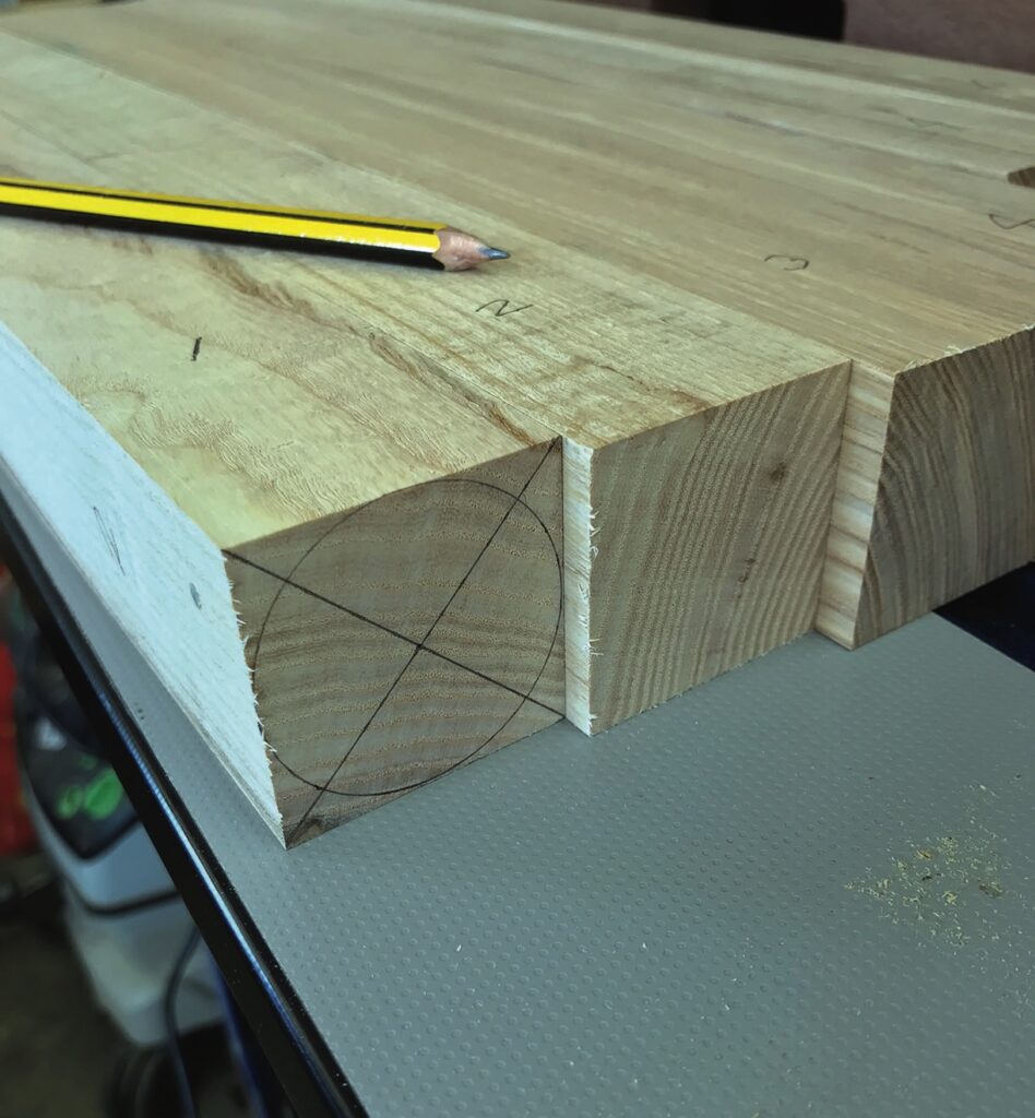
No matter what size leg or spindle you’re intending to make you’re going to need to start off with a square section blank. The example shown here has been cut from a board approximately 200mm wide and 50mm thick. It’s quartersawn and ideal for something like a leg vice chop or chair seat as the growth rings pass from opposite faces. Reduced into four separate square blanks across its width and ready to thickness down to 45mm square, the growth rings are still passing from opposite faces and as such wouldn’t make for a good choice aesthetically for four square legs. Two of the faces would display a cathedral grain pattern while the other two would feature pin stripes. But, as we’re going to turn these squares into octagonal shapes we can pretty much assume that at least six of the eight sides will have a consistent stripy appearance. Having found the centre of our square we can now draw a circle with a diameter equal to the width across two opposing faces of our octagon. Or put more simply, just touching the faces of our square. Note that at this point the size of the square doesn’t need to represent the size of the octagon, it just needs to be bigger or equal. Making repeat passes on any machine requires a good system for identifying a whole number of things, such as which face has been worked, which face is being used as a reference and even which direction the component needs to be passed over or under (or past) the tooling. You could opt for a simple squiggle or a continuous band around the square but nothing beats a good old-fashioned sequence of numbers. If you’re consistent with your numbering it will tell you at a glance the direction as well as the orientation in respect of rotation. It’s easier to appreciate in practice than to describe in theory by the way. One of the benefits of machining identical components is that not every component needs the full complement of marks. In this case just one will do.
Alternative layout
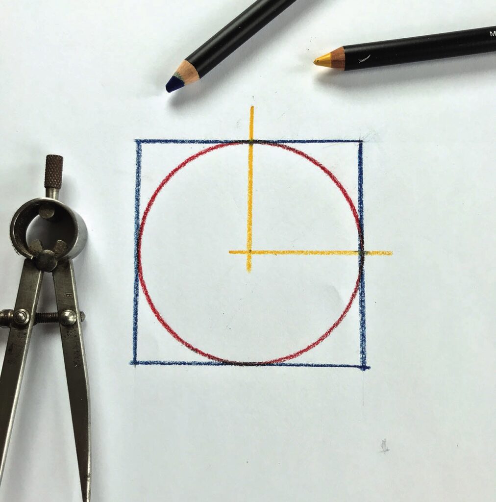
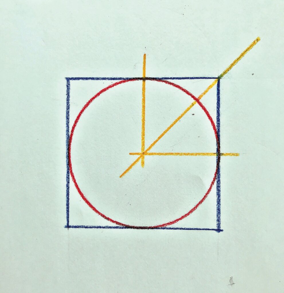
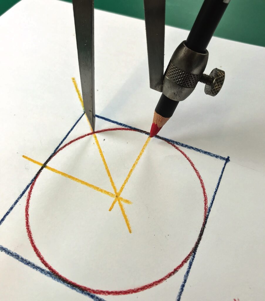
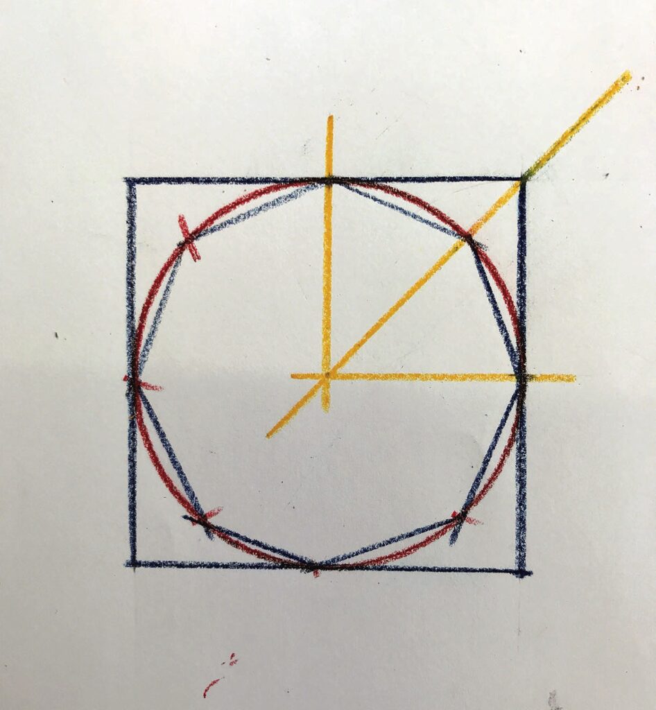
The geometry for creating an eight-sided polygon is quite straightforward if you want to draw it out with a compass and square.
Good first pass
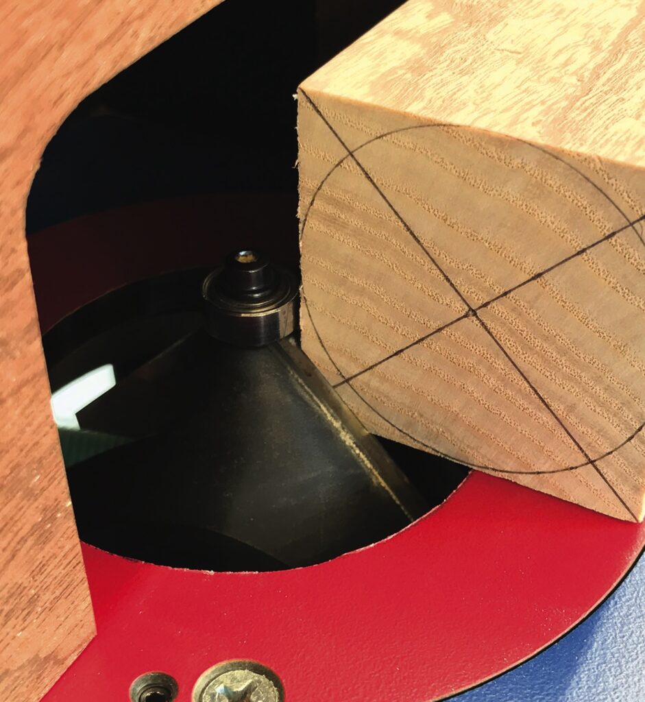
The cutting geometry required to convert a square column into an octagonal one couldn’t be simpler as the tooling will take care of the maths for you. All you need is a basic 45° chamfer cutter, preferably with a bottom-mounted bearing. I know, in the picture the bearing appears at the top but remember the router is inverted in the table, which now makes the bottom the top. Note that in router catalogue terminology cutters are generally referred to as having their shank pointing skywards. I don’t know who makes the rules but that’s what they are.
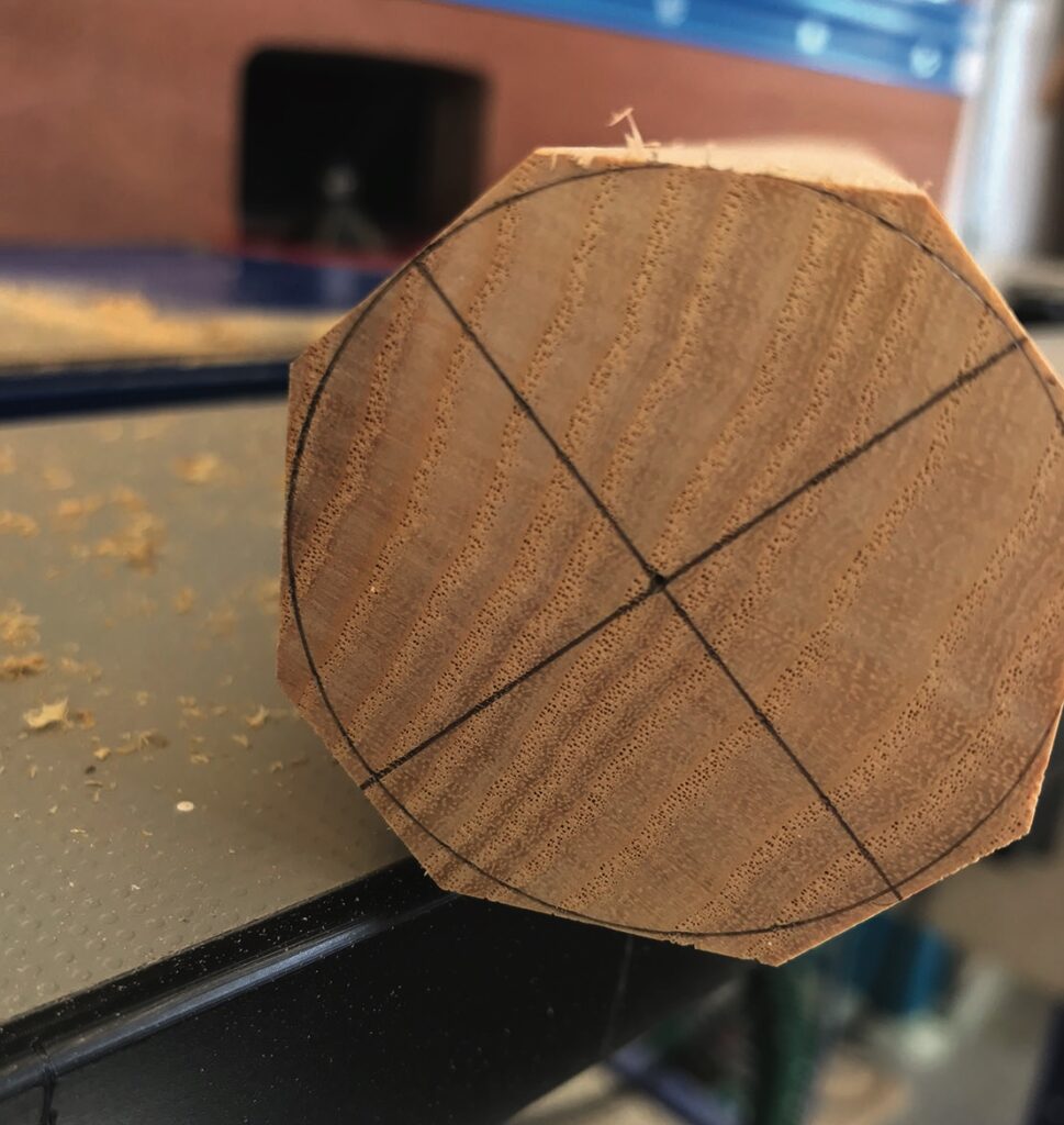
If your cutter has a bearing, set your fence to be in line with it as it will offer extra support to the workpiece and in some instances negate the need for a breakthrough fence if the cutter aperture is fixed as in this example. More complex versions comprise two separate fence sides that can be opened up or closed to suit the tooling. The downside of these is that they tend to have quite low fences that impose other restrictions. To my knowledge Festool is the only manufacturer to buck this trend. The object of the exercise is to chamfer the corners of the square to the depth of the circle. The first pass isn’t critical in terms of accuracy if the cutter is capable of removing all the material you need in a single pass. However, you may want to creep up to the finished dimension in stages leaving the finest cut for the last pass to achieve the best finish. Moving the blank slowly will also result in finer machine marks and help to avoid any furring up of the grain or breakout. After each pass rotate the blank a quarter of a turn to present a fresh corner to the cutter. After a complete round at one setting raise the cutter closer to the circle and repeat. When the cutter reaches the circle the octagon is complete. If you’re worried about any unevenness you can make extra passes rotating the blank 1/8th of a turn. This will likely remove some or all of your pencil marks.
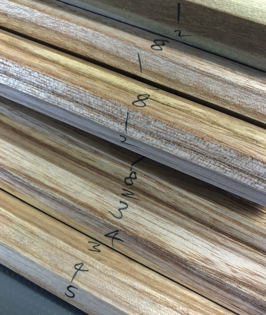
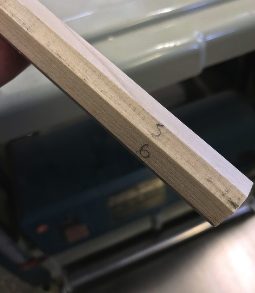
Further adjustment
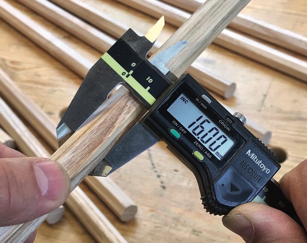
Further adjustments can be made using the same method on the router table but in this configuration the machine is not really functioning as a precision instrument. Feather boards, push sticks and other devices will certainly introduce a good level of consistency but for an exact finish you might want to turn to your thicknesser. When you want to run objects through the thicknesser that don’t have parallel faces you need to make up a cradle or sliding carriage to support them as they pass through. Octagons, however, have four pairs of parallel faces so can be thicknessed or in this case re-sized quite easily. Before doing so you’ll need to decide the new overall thickness between any two parallel faces. Let’s say it’s 16mm and the octagon sections are currently standing at 18mm. Number the faces 1 to 8 and set the thicknesser to 17mm and pass each component through taking a pass at position 1 to 4. If you haven’t worked it out yet the amount you’re removing is half the total amount needed to achieve the new thickness.
The number sequence is really important at this stage as the octagon will start to look quite misshapen. Ignore the proportions and trust the numbers as it is easy to make a mistake. For the next and final step you’ll need to adjust the thicknesser to the final dimension – 16mm – and pass the blank through the machine in positions 5 to 8.
It’s worth mentioning at this point that it’s not uncommon for thicknessers to start or end a pass with a little indent of around a millimetre deep, anything from 50–100mm long at either end. Commonly referred to as snipe it happens as a result of the knives not being set properly in relation to the out feed table during planing mode. The discrepancy is then mirrored to the opposite face when it comes to thicknessing. Be aware you may experience a similar quirk when routing. While it’s annoying it’s not the end of the world as long as you accept that the first and last 100mm of the board is not to the finished dimension. Similarly when thicknessing thin stock in soft material the ends can get slightly compressed by the feed rollers also giving a false reading. For an accurate picture of what’s going on check your dimensions from the middle of the board.