Ornamental Turning Made Easy – more:
Chris Hart covers the components, their function, how they interact and how to make the bespoke parts to fit your lathe.
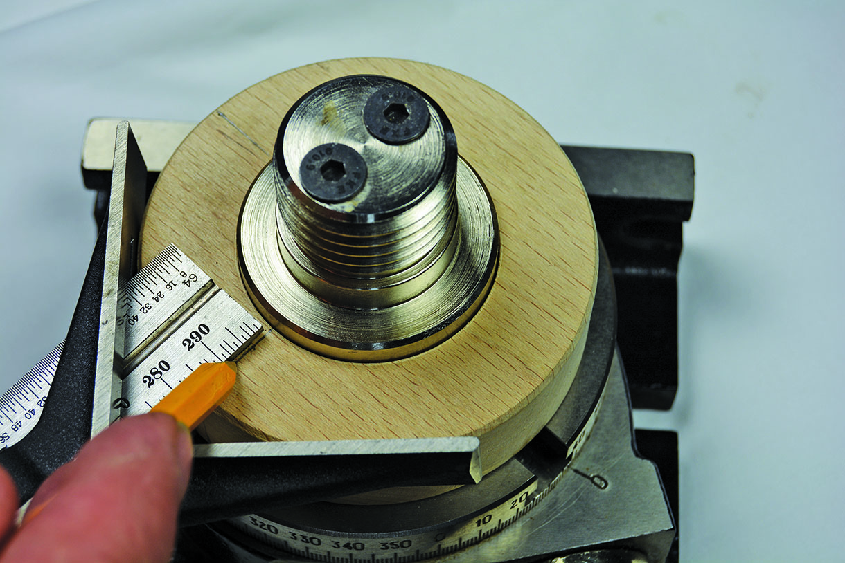
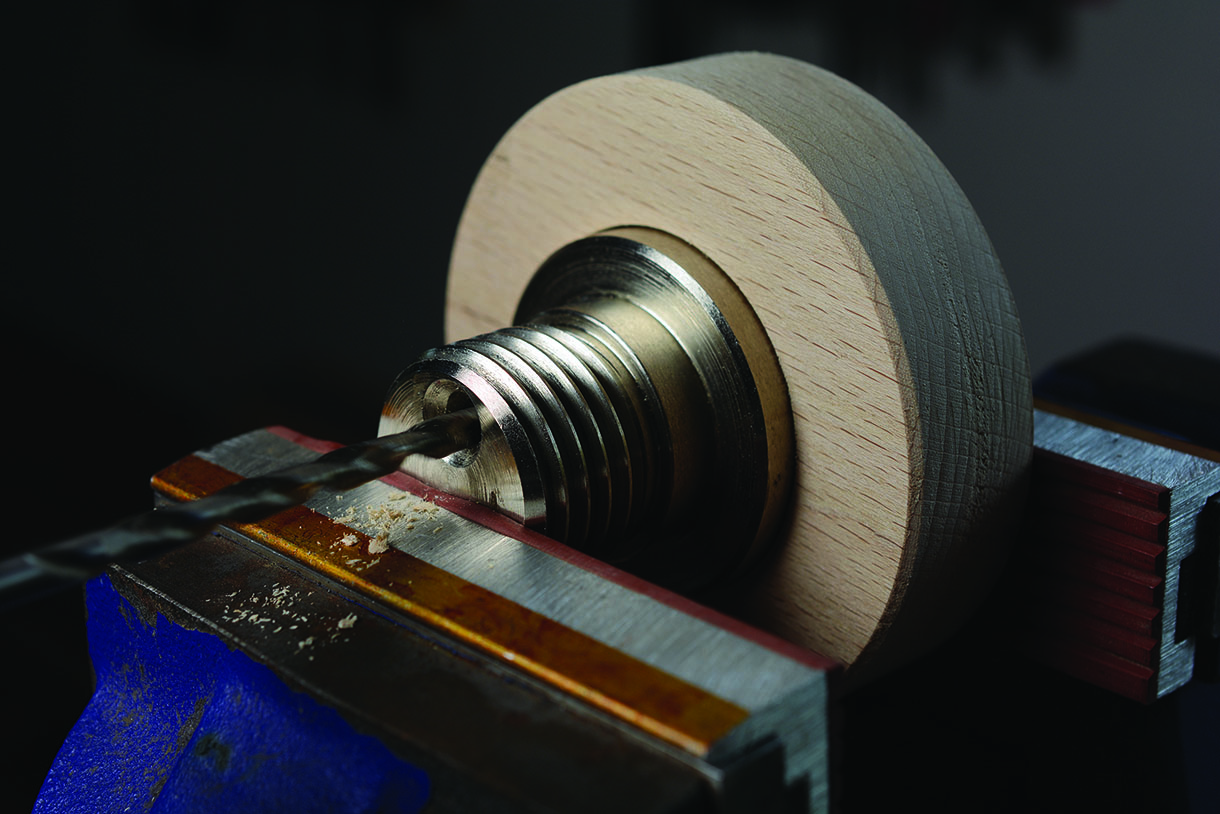
Chris Hart marking the bolt hole positions on the chuck mount with the centre finder from a combination tool set, prior to drilling. The penultimate operation in making the chuck mount
I will cover the purchase of the individual components required in detail, their function, how to make the cutting tools from HSS blanks and keeping them sharp. At this point, I must stress the need for accuracy in any parts you make or components you purchase. Woodturning is not, by nature, a precision operation. Shapes are achieved by freehand control of the tool with the work spinning, however ornamental turning is, in fact, a machine operation requiring only shallow cuts by a spinning cutter applied to a static workpiece. The cutting process is achieved by advancing the cutter in to the workpiece in precise measured increments. The aim is to produce symmetrical patterns hence the need for absolute accuracy. The key areas to consider are concentricity of the chuck mount and rotary table, alignment of the headstock with the assembled unit also with the baseboard with bed bars. When researching the market, accuracy was the primary objective. The components specified have proved to be excellent, exceeding my expectations without compromising the budget, so am happy to recommend them.
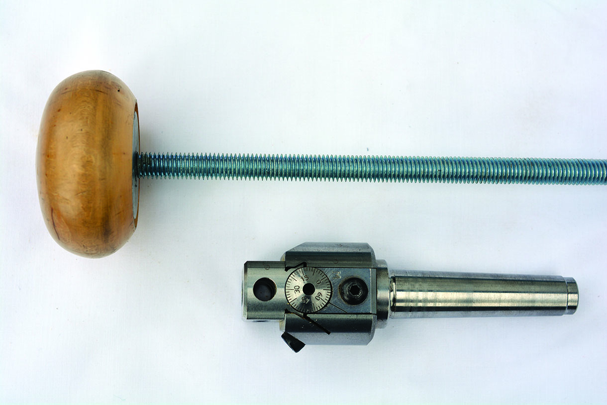
The boring head and draw bar
The boring head is an industrial engineering tool mainly used in vertical milling machines for boring precision holes in metal. The tool consists of a Morse Taper shank with a head attached, it has three slots, which accept 8mm HSS tool bits, two extending parallel with the lathe axis and one which is offset at 90° to the lathe axis. The head is mounted on a dovetail slide and when it is extended outwards will scribe a circle, which is offset in relation to the lathes axis. The central slots capacity ranges from dead centre to 20mm, which will scribe or cut circles from 1–40mm diameter in small increments. One full turn of the adjusting screw is 1mm, the outer slot’s range is 10–30mm. The slot, which is offset 90° to the axis is for cutting objects along the axis that also has 30mm of adjustment.
The Morse Taper is threaded M10 and when fitted in the headstock it is secured by a drawbar screwed into the Morse Taper shank preventing the head from working loose.
The drawbar is made from a 10mm threaded rod available from most DIY stores measured in situ and cut to correct length. Two nuts with a spring washer between them are locked together on one end (alternatively a long bolt can be used). Turn a dome shaped end, the opposite side is drilled to make a jam fit for the nuts then fill the voids around the nuts with a strong epoxy resin and cap off with a large washer.
The boring head and draw bar
The compound table
The compound table presented no problem. It is a quality product made in Germany and available for a very reasonable price, as I have been a long term fan of German engineering expertise and used other tools from the same stable. I was happy to plum for this without reservation. An added bonus was the fact that I found the product on eBay from a German supplier, with a huge saving on the same product that’s available in the UK. This does the job admirably and exceeded my expectations. The table is 250mm square has 150mm of total travel, being 75mm either side of the centre in both the X and Y axis with a flat platform with three T slots for securing auxiliary equipment.
The role of the compound table is to provide a flat and level surface to mount the rotary table on and position the work in relation to the cutter and feed the work into the cutter.
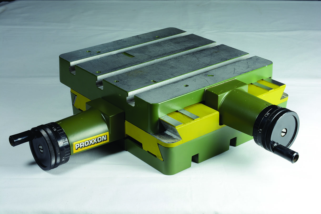
The compound table
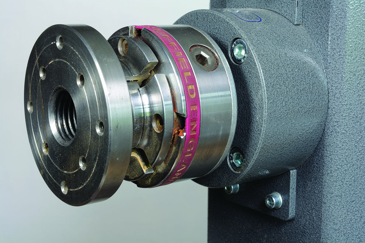
The rotary table
The rotary table bolted onto the compound table fitted with a chuck mount has two functions: to hold the chuck and rotate it in measurable increments, thereby presenting a fresh surface to be cut, creating the pattern. The rotary table and the boring bar are manufactured in India by Sorba and are widely available
across the UK and, indeed, the world under various brand names.
The chuck mount
Mounting the chuck presented the biggest issue for me, although it is possible to purchase rotary tables with chuck mounts, they were all for industrial engineering use and not with the size and thread pitch
I needed. While it is possible to have one made by local toolmakers the cost was prohibitive, also this option may not be available to everyone. I had an idea for some time that I could adapt one from a product sold as the ‘Chuck Hub’, used for storing spare chucks. I gave it some thought and experimented with a few prototypes and came up with a process which would provide me with the concentricity I required. I have stressed throughout this series, accuracy is paramount and transferring the work piece mounted on the chuck it was turned on is the only way to maintain the integrity of the concentricity and ensure the pattern is uniform all over.
To attach the Chuck Hub to the rotary table you will need to make a suitable mount by using a recess for the hub boss to sit, drilling the wood for the fixing screws and turning a location pin.
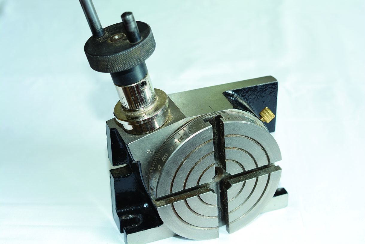
The rotary table
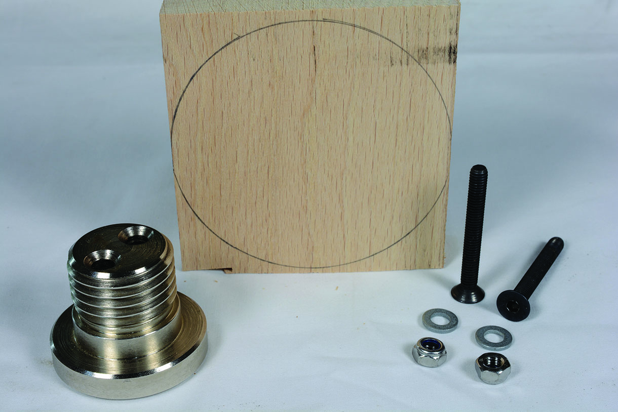
1. For the chuck mount I used a piece of quarter sawn beech (Fagus sylvatica), but as with the base, ply or any stable close grained hardwood will be okay. The first prototypes I made were 25mm ply
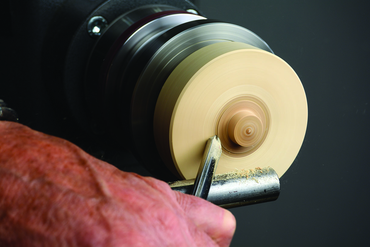
2. Plane the wood to 25mm uniform thickness and cut to 100mm diameter. Mount on a small screw chuck/face plate and true up the circumference
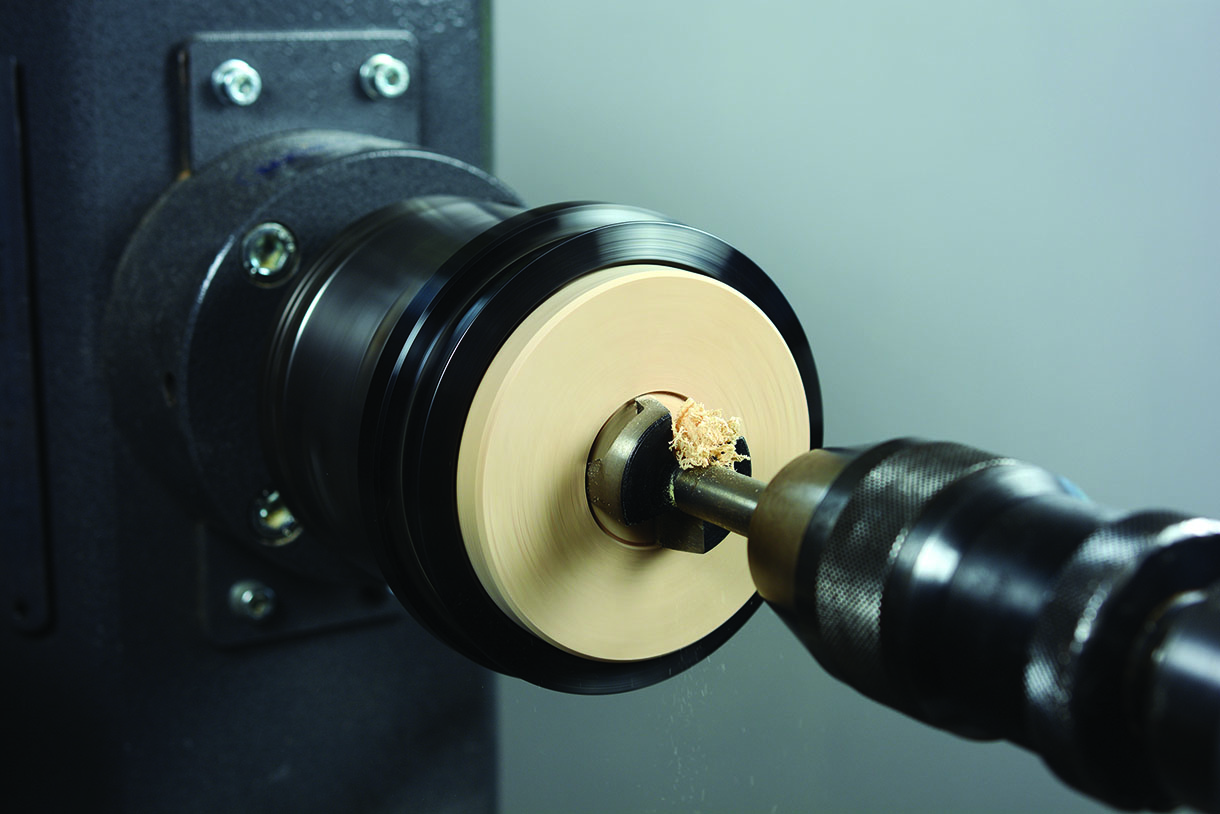
3. Next mount onto a chuck and, using a 35mm Forstner bit, cut the recess for the hub mounting screws
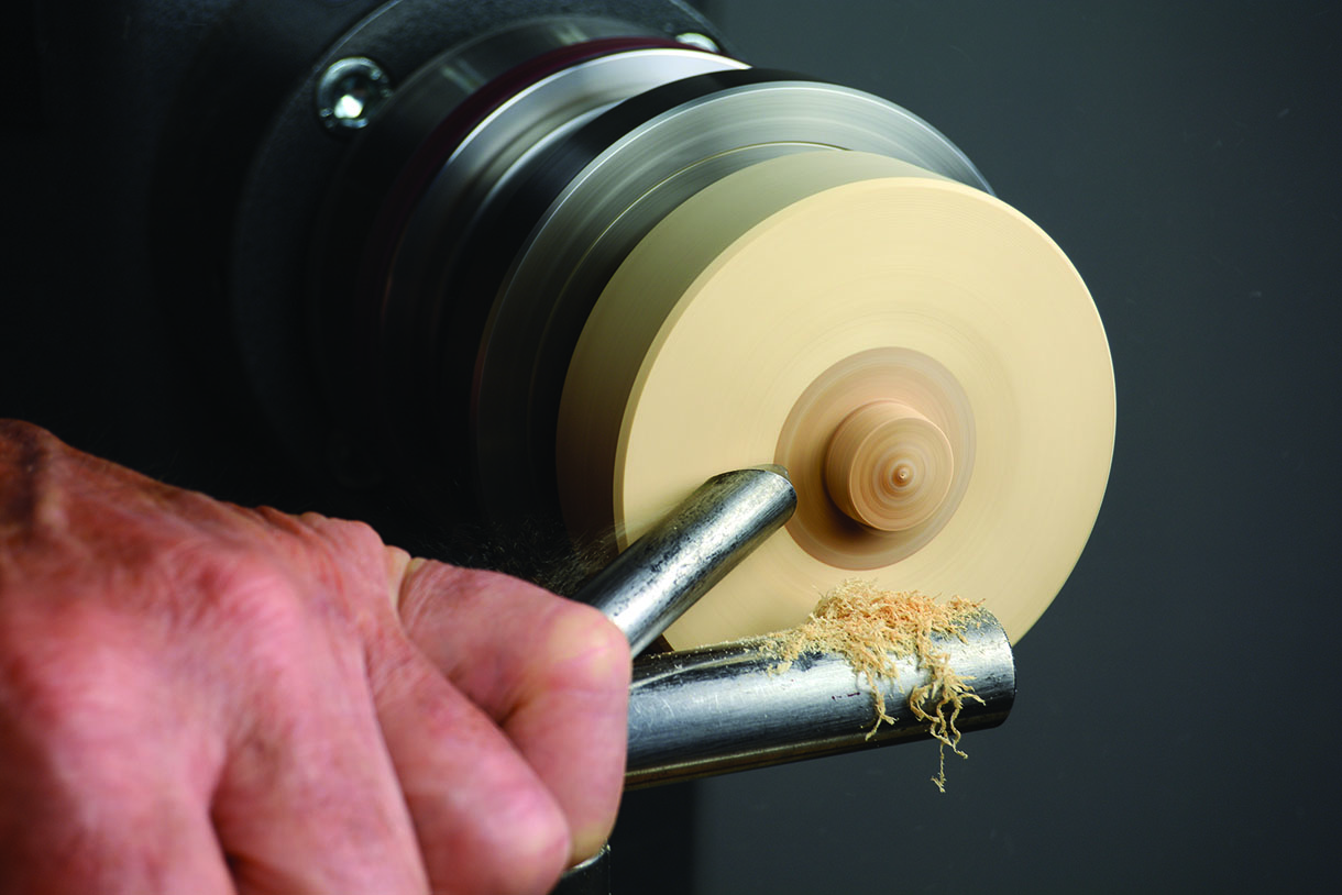
4. Reverse the piece in the jaws and cut a recess so the boss fits snugly, using plunge cuts tidying and squaring the base so that the boss sits squarely in the recess. This can sometimes be difficult to achieve so the answer is to dish the centre leaving a small ring around the perimeter, which is easy for the cut to run true and the boss will sit on this. The boss sitting snugly is vital because, when mounting the chuck, it can generate high torque values and may cause the mount to twist, however if it is restrained within the recess while the retaining screws may twist, it will not throw the mount off centre. Turn a plug to fit the smaller of the recesses measuring 35mm diameter and 20mm long this will form the location pin
5. It’s time to fix the chuck hub to the base. Insert the boss into the recess and hold securely in a vice using face plates to protect the surfaces, marking and drilling clearance holes to accommodate 6mm diameter screws. Fix the hub into the recess and secure with 6mm countersunk screws and Nyloc nuts
6. Now insert and glue the plug you made earlier. The next steps and sequence are vital because the objective is to ensure the chuck hub is concentric with the rotary table, which means getting the hub and locating pin to run true and in the same plane
7. A small faceplate now needs to be mounted in a chuck by gripping the boss, not an everyday occurrence in woodturning because it’s steel on steel. However, I used standard 50mm jaws and the diameter of the boss is 50mm so a perfect fit. I did not encounter any issues with this set up; an alternative is to use a set of engineering jaws, such as those Axminster produce for their range of chucks
8. Screw the newly made chuck mount into the faceplate. If the machining has been accurate it will run true. The success or failure of this project depends largely on how accurately you are able to mount and turn the required components. None of the cuts required are particularly challenging; they just need care and concentration
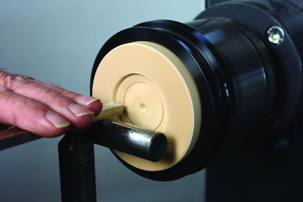
9. True up the circumference if necessary, at the same time true up the plug, turn and trim to size. Carefully measure and be accurate with the sizing aiming for an interference fit (mine is 18mm diameter). This is the location pin, fitting the centre of the rotary table ensuring concentricity
10. Undercut the insert so the face will fit flush with the rotary table
11. If the back is running out then this will need truing up again. The best way is to dish it slightly with very light sheer cuts using a bowl gouge or scraper
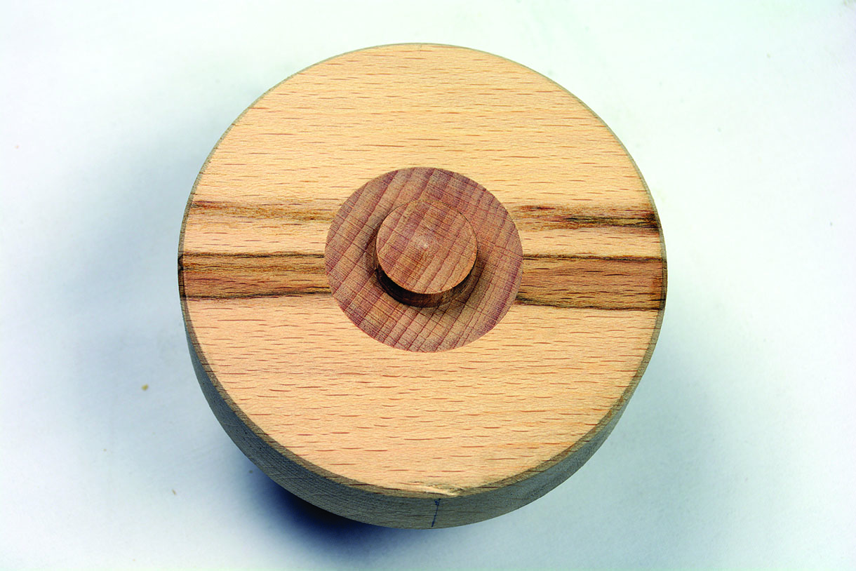
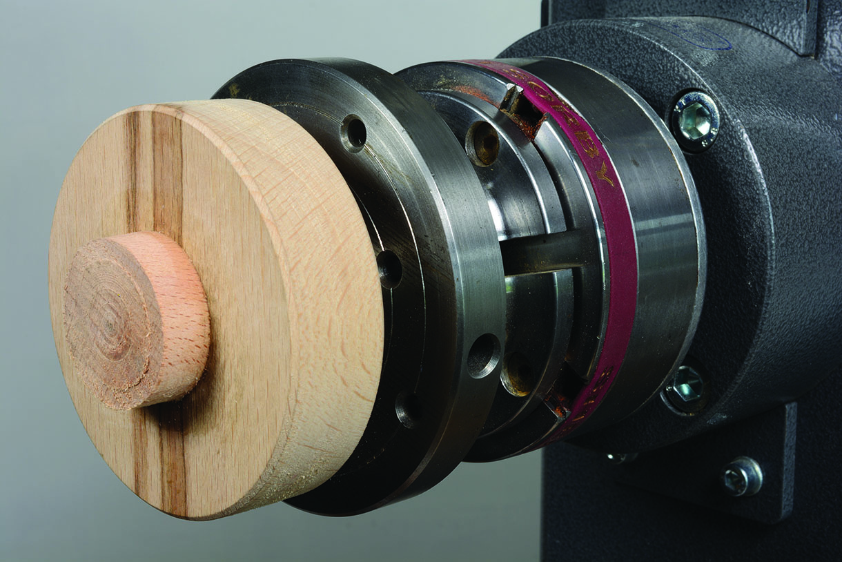
12. If the machining has been accurate it will run true on the rotary table and the back should look similar to the one you see in here
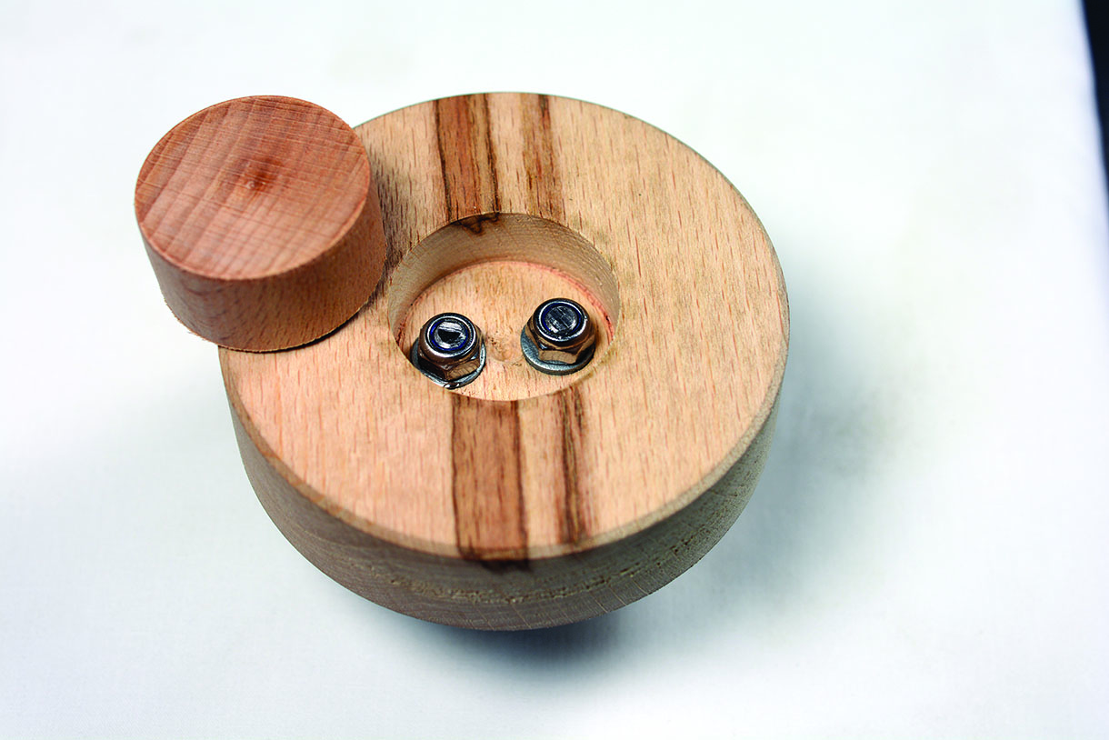
13. Offer the chuck mount to the rotary table, the pin should be a push or interference fit. Mark the positions for the bolt holes on the top then transfer to the underside
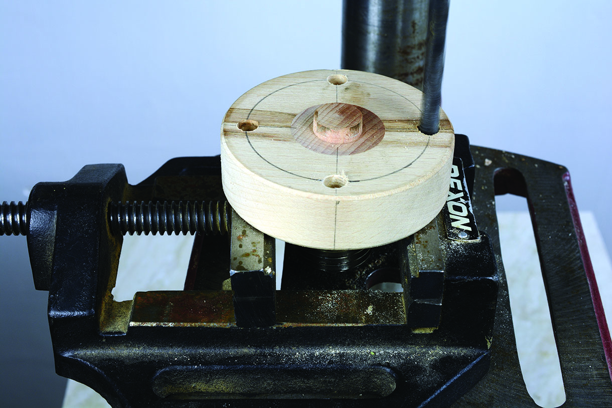
14. By doing it this way it will enable the boss on the hub to be held in the drilling vice. Be sure to allow clearance between the hexagon bolt heads and the boss of the hub
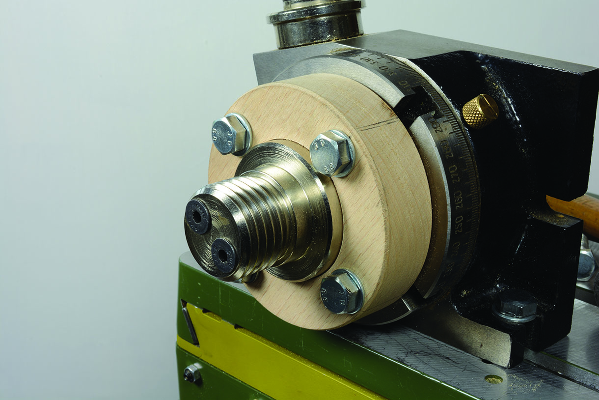
15. The finished chuck mount looks similar to the example shown here, mounted on the rotary table. The most difficult part is finished
Alternative materials
It is possible to make the whole chuck mount from a single block of wood. However, finding a suitable timber is the issue, lignum vitae (Guaiacum officinale) will certainly hold a large thread and is robust enough to withstand the rigors of the tasks involved, the problem is finding a piece which is dry enough, I have only encountered it partly seasoned apparently never really dries, if the moisture content was too high when turned it would certainly warp in service ruining the concentricity, oak is hard and durable enough but will
not hold a large thread, there were lots more species and so it went on in this vein. I then considered materials like hard nylon or other synthetic materials, however, apart from seeing John Berkley thread cutting similar materials, I have no experience of them, or wish to gain any, while trying to complete a project. What about aluminium? I am sure the combined skill set and knowledge of the readers of Woodturning will have the answers, please let me know.
Making the baseboard
The function of the baseboard is simple and that is to provide a solid platform for the compound table, which in turn, is the base for the rotary table that houses the chuck. It establishes the centre height and also enables the work to be presented to the cutter at desired angle. In its simplest form the base consist of two parts, the base with a strip screwed to the underside to locate it between the bed bars forming a base for the second board, which the compound table is bolted to. The boards are connected by a centralised bolt to lock the boards in place.
The overall thickness of the two boards is determined by subtracting the overall combined height of the compound table and the centre height of the rotary table from the centre height over the bed. The final two pieces before assembly is a pass a 10mm bolt through the top board, hammer into the recess and glue with epoxy. From a length of mild steel 35 x 6mm, available in 1000mm lengths from DIY stores. Cut two pieces about 20mm wider than the gap in the bed bars, if your lathe has strengthening filets along its length make sure they don’t foul these. Drill a 10mm clearance hole in the centre of these, pass a bolt through each hole and secure with a spring washer and a nut. Drill a corresponding hole in the baseboard, pass the bolt, through and screw in place using a female Bristol leaver or plastic knob.
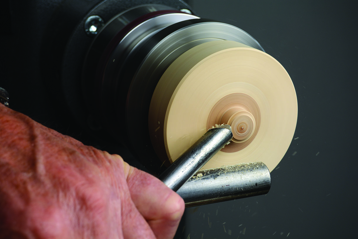
A few notes on making the base, normally when making jigs I would use biscuit joints and glue. However, screws keep it simple so if you find the base is not quite right it is easy to adjust and reassemble, also if you want to use it on another lathe the only thing different will be height and the gap between the bed bars, with screws all these things are easily changed. You can also drill and tap the retaining straps and use a male Bristol leaver. Originally I used a Bristol leaver on the central bolt however, the gap was quite small, so I swapped to a nut, using a ratchet and socket. The image shows three examples of baseboards. On the left is the simplest form, a board with locking leavers. On the right is a baseboard with a raised platform to accommodate a 250mm centre over the bed and the centre is an offset baseboard with a raised platform. The height and the offset allows the full swing of the lathe to be utilised for decorating the faces of platters or bowls using the cutter in the boring bar in offset position 90° to the lathes axis. An example of the offset baseboard in use can be seen at the beginning of this article.
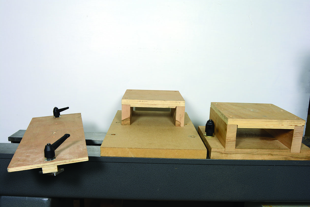
Left to right: Universal base, offset baseboard, standard baseboard
Making the tool bits
The tool bits are 8mm diameter x 100mm HSS round tool steel. I profiled each end and then parted off one from each end, then profile the remaining middle piece, making three tools approximately 30mm long. The reason for profiling before cutting to size is, at 100mm, they are much easier and safer to handle and will sit in a Tormek or Robert Sorby jig to enable the relief angle to be ground. The angle itself is not important; it is there to provide relief from the cutting edge. However, it will determine the tip on a basic tool, which is a point, the angle depends on how thick a line you want to scribe more of other shapes or profiles later.
The process begins by shaping the relief on the underside. I use two methods: a Tormek bench grinder kit for dry grinding with a gouge jig and I’ve also used a Robert Sorby pro-edge, both producing a gouge shape profile. Alternatively, I use a Robert Sorby pro-edge with a skew chisel jig, producing shapes similar to skew chisels. Interchanging or combining the machines will sometimes produce a better result. Wet grinding is unsuitable because it’s too slow. Various shapes can be achieved by changing the profile of the cutting edge showing a ‘flat’ profile, which forms a truncated point.
This will cut angled sides with a flat bottom. Next the top of the tool needs to be relieved to produce the cutting edge; again a choice of methods using either machine, the dry grinding is achieved freehand, whereas the Sorby utilises the gouge jig to hold the tool.
Grinding the top is also the sharpening method; all that is needed is the lightest of skims. Alternatively, a light rub with a diamond stone is an effective method. All of the above can be achieved by ‘freehand grinding’ on a bench grinder or belt sander, however it should not be attempted unless you have the skill, experience and are comfortable with the process. Finally, the tool needs to be parted from the blank; I use a small angle grinder with a metal cutting disc. Alternatively, small rotary machines such as dremel and other similar tools may be used.
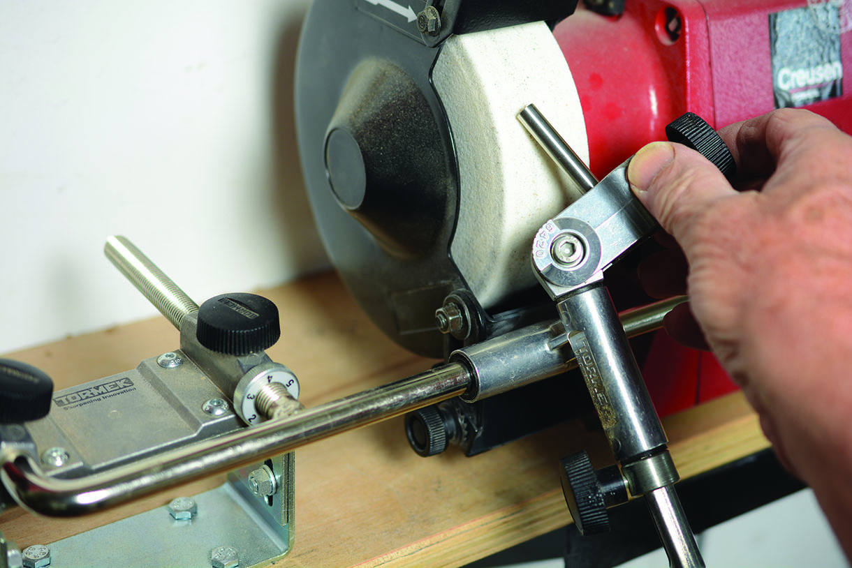
Tormek’s jig is adapted for dry grinding
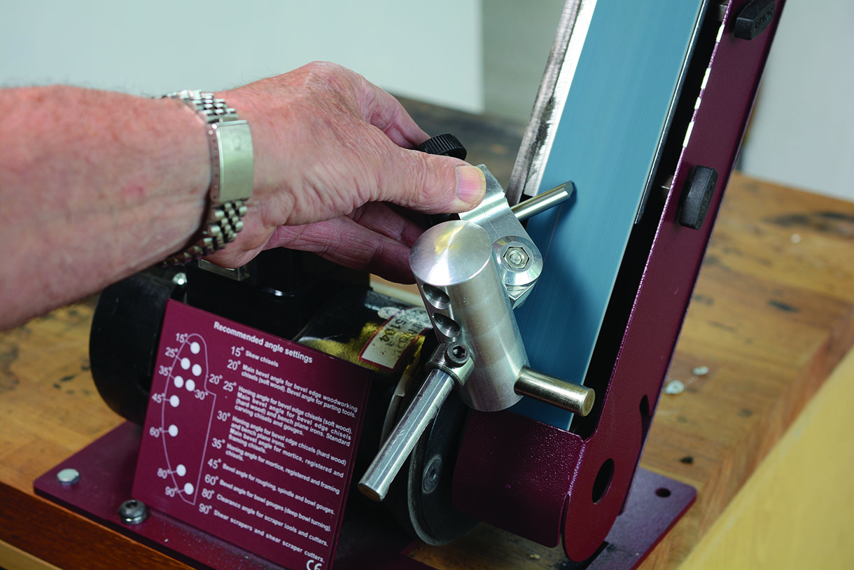
Profiling tool on pro-edge
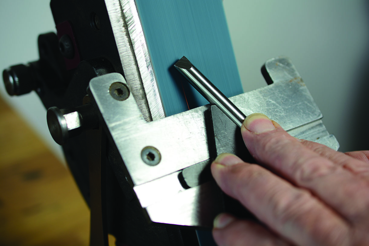
Profiling on pro-edge with skew jig
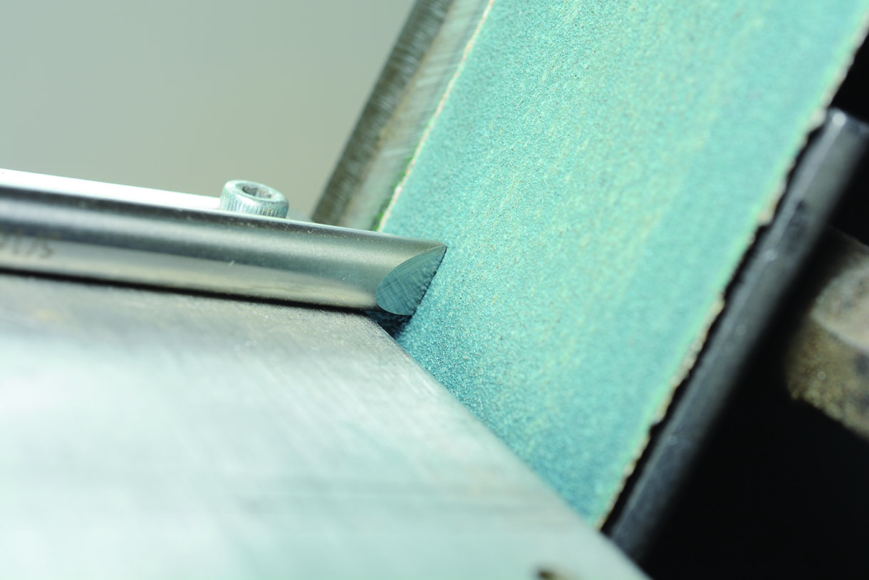
Truncating a point tool on pro-edge
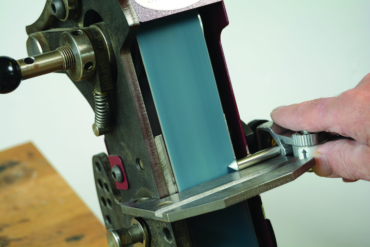
Relieving top of tool on pro-edge
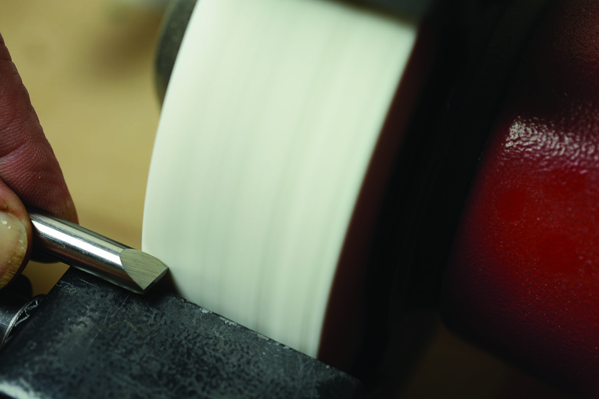
Relieving top of tool on grinder
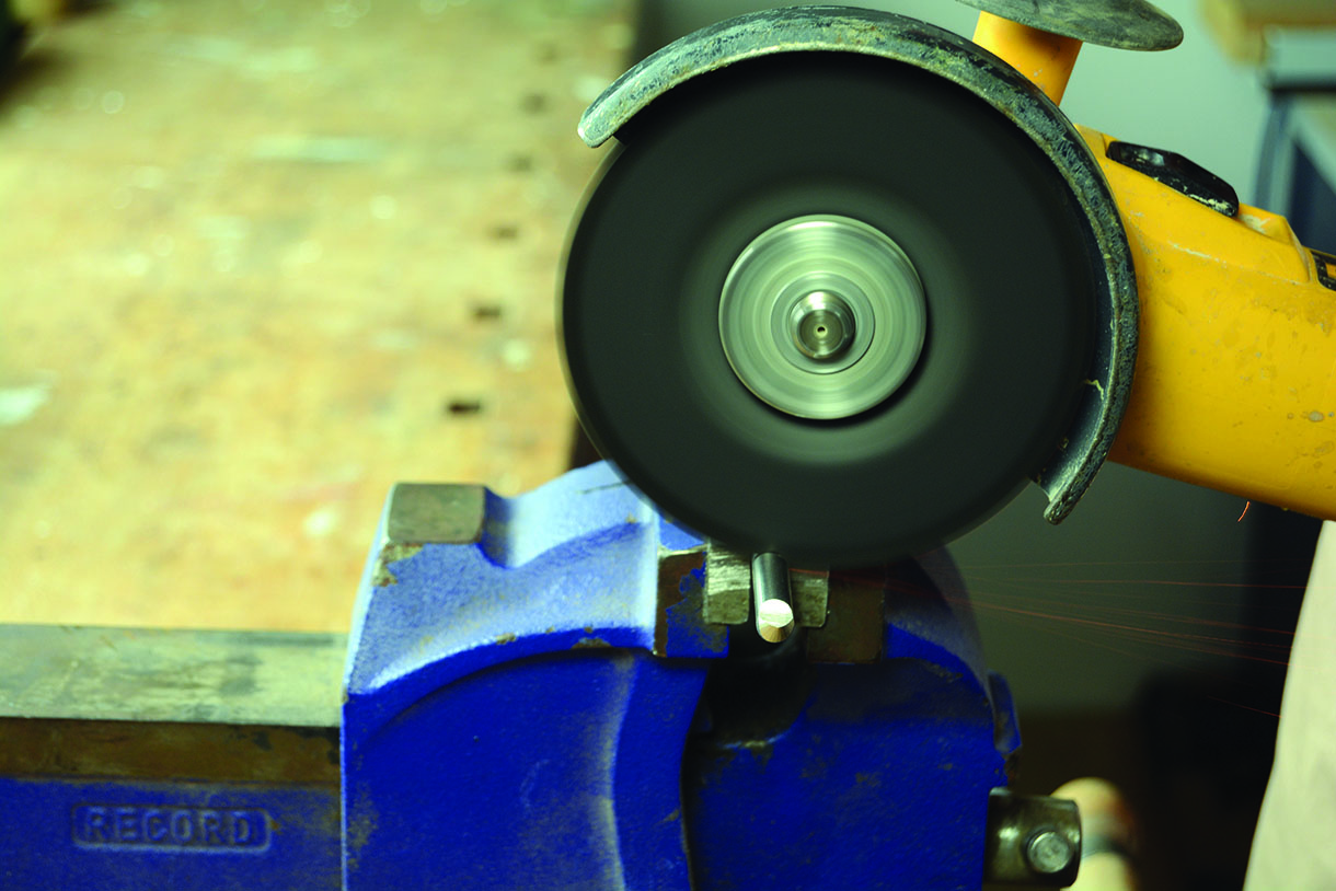
Parting off the tool
Top tip
Remember grinding wheels will always produce convex forms, while belt type operations will produce flat forms.
Health and safety
Please note goggles and/or face protection should be worn throughout all of these operations. While these grinding operations are considered standard workshop practice great care must be taken. Therefore if you’re uncomfortable with any of them an alternative method should be sought.

")
